//--------------- Fig. 11.1-16a /prism/
#version 3.7
#include "colors.inc"
#include "textures.inc"
#include "stones.inc"
global_settings
{assumed_gamma 2.2}
camera{
location<5,-20,10>
sky<0,0,1>
right <-image_width/image_height,0,0>
look_at<-0.3,0,1.3>
angle 25
}
light_source {<500,-500,1000> color White*1.5}
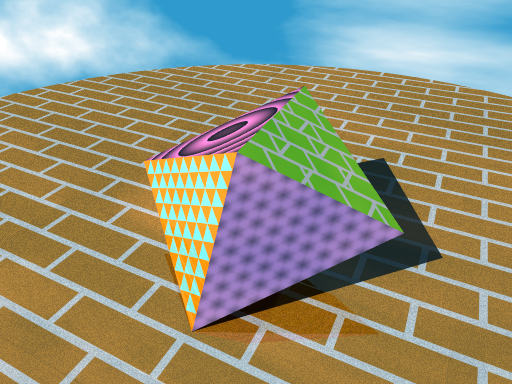
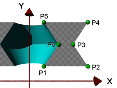
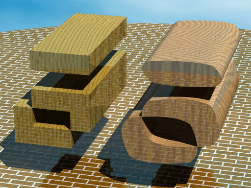
//====================== define /// sweep triangle ///
#declare prism_1a=
prism{
linear_sweep
linear_spline
0,3.5,
4, <0,0>,<1.5,0>,<0.75,1.3>,<0,0>
}
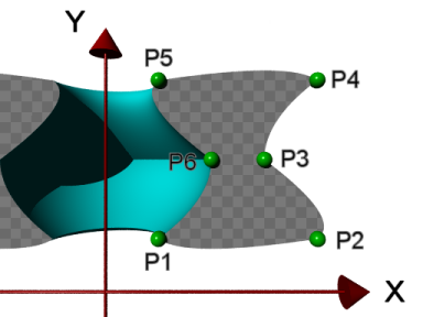
#declare prism_1b=
prism{
linear_sweep
quadratic_spline
0,3.5,
5, <0,0>,<1.5,0>,<0.75,1.3>,<0,0>,<1.5,0>
}
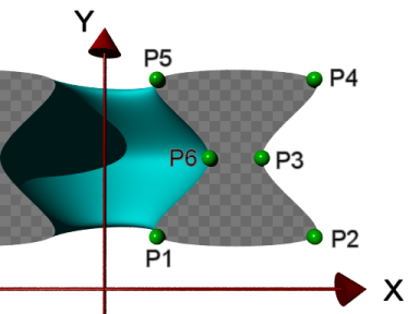
//====================== define /// sweep rectangle ///
#declare prism_2a=
prism{
linear_sweep
linear_spline
0,3.5,
5, <0,0>,<1.5,0>,<1.5,1>,<0,1>,<0,0>
}
#declare prism_2b=
prism{
linear_sweep
quadratic_spline
0,3.5,
6, <0,0>,<1.5,0>,<1.5,1>,<0,1>,<0,0>,<1.5,0>
}
//====================== define /// sweep pentagon ///
#declare prism_3a=
prism{
linear_sweep
linear_spline
0,3.5,
6,<0.2,0>,<1.3,0>,<1.5,0.8><0.7,1.3>,<0,0.8>,<0.2,0>
}
#declare prism_3b=
prism{
linear_sweep
quadratic_spline
0,3.5,
7,<0.2,0>,<1.3,0>,<1.5,0.8><0.7,1.3>,<0,0.8>,
<0.2,0>,<1.3,0>
}
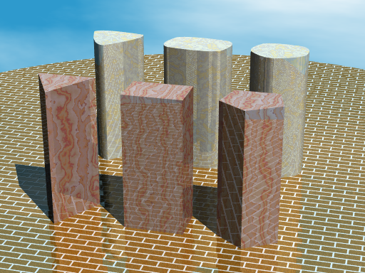
//============================== place Object 1
union{
object{prism_1a rotate x*90 translate<-3.5,-2,0>}
object{prism_2a rotate x*90 translate<-1,-2,0>}
object{prism_3a rotate x*90 translate<1.3,-2,0>}
texture {T_Grnt29 scale 0.5}
finish{phong 1 reflection 0.2}
}
//============================== place Object 2
union{
object{prism_1b rotate x*90 translate<-3.5,2,0>}
object{prism_2b rotate x*90 translate<-1,2,0>}
object{prism_3b rotate x*90 translate<1.3,2,0>}
texture {T_Grnt1 scale 1}
finish{phong 1 reflection 0.2}
}
//----------------ground
disc{0, <0,0,1>, 12
pigment{brick White, CoolCopper*0.7 scale 0.08}
normal{brick 0.01 scale 0.1}
finish{reflection 0.3 crand 0.1}
}
//----------------sky
sky_sphere{
pigment{
wrinkles
color_map{
[ 0.4 SkyBlue]
[ 0.9 White ]
}
scale <1, 0.2, 0.2>
}
}