3. 座標系と変形
3次元空間で物体などを配置するとき、その位置設定には空間の座標系を使う。シーンは、すべて3次元座標系に従って記述される。また、物体やテクスチャなどの変形にも座標系は密接に関わる。このセクションでは POV-Ray の座標系と変形について示す。
3.1 座標系
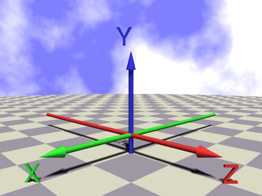
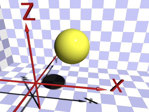
物体、光源、カメラなどは、すべて3次元座標系を用いて設定する。3次元座標系には左手座標系と右手座標系がある。左手座標系(y-up) POV-Ray標準右手座標系(z-up)
図3.1a 左手座標系(y-up)
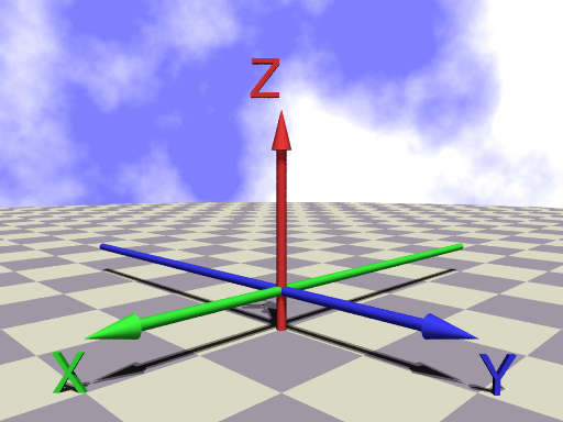
図3.1b 右手座標系(z-up)
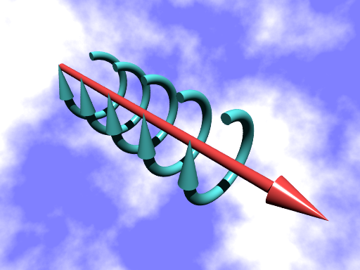
図3.1c 左手系の正の回転方向
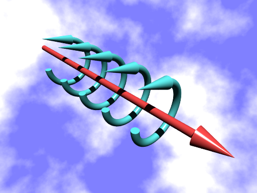
図3.1d 右手系の正の回転方向
また、回転方向は親指を軸の + 方向としたときに他の指が巻きつく方向になるが、これも右手系と左手系では逆向きになる(図3.1c、図3.1d)。
POV-Ray のデフォルト座標系は左手系(y-up)である。過去においてはCG分野では左手座標系が使われてきたが、現在では右手系が標準となっている。このマニュアルでも、 右手座標系 (z-up)を使用して説明する。
※ 座標系は camera 文で設定 ▷「5.1 座標系の設定」 参照
座標系内の位置は、3成分ベクトルによって設定する。3つの成分はそれぞれ x、y、z の座標値になる。例えば、ベクトル<1,2,3>は、原点<0,0,0>から x 方向に+1、y 方向に +2、z 方向に +3 の位置となる。
∇ POV-Rayソース: 図3.1a 左手座標系
//-------------------- Fig. 3.1a left hand
#version 3.7
#include "colors.inc"
#include "textures.inc"
global_settings
{assumed_gamma 2.2}
camera{
location<1.7,1.7,0.8>
sky<0,0,1>
right <-image_width/image_height,0,0>
look_at < 0, 0, 0.6 >
angle 60
}
light_source {<200,300,1000> color White*0.5 }
light_source {<300,400,1000> color White*0.5 }
light_source {<300,300,1> color White*0.5 shadowless}
//========================================= axis
#declare SS = 1.5;
#declare XAC = rgb<0.2,0.8,0.2>*SS;
#declare YAC = rgb<0.2,0.2,0.8>*SS;
#declare ZAC = rgb<0.8,0.2,0.2>*SS;
#declare A_l = 0.8;
#declare A_r = 0.025;
#declare Arrow =
object{
union{
cylinder{-z*2,z*A_l,A_r}
cone{z*A_l,0.05,z*1,0}
}
}
#declare Front = <90,0,135>;
union{
union{
object{Arrow rotate y*90} // <<<------ x-axis
text{ttf "cyrvetic.ttf","X",0.1,0
scale 0.2
rotate Front
rotate z*180
translate <1.0,0,-0.2>
}
pigment{XAC}
}
union{
object{Arrow translate z*-0.1} // <<<--- y-axis
text{ttf "cyrvetic.ttf","Y",0.1,0
scale 0.25
rotate Front
translate <0.11,-0.100,0.95>
}
pigment{YAC}
}
union{
object{Arrow rotate x*-90} // <<<------ z-axis
text{ttf "cyrvetic.ttf","Z",0.1,0
scale 0.2
rotate Front
translate <0,1.0,-0.2>
}
pigment{ZAC}
}
finish{phong 1 reflection 0.1}
translate z*0.2
}
//---------------------ground checker
#declare C1=rgb<0.95,0.9,0.98>;
#declare C2=rgb<1,1,0.9>*1.3;
plane{z,0 clipped_by{sphere{0,10}}
pigment{checker C1, C2 scale 0.5}
}
//--------------------------sky
sky_sphere{
pigment{
wrinkles
color_map{
[0.3 White*1.2]
[0.7 color rgb<0.5,0.5,1.0>]
}
scale 0.3
}
}
∇ POV-Rayソース: 図3.1b 右手座標系
//-------------------- Fig. 3.1b right hand
#version 3.7
#include "colors.inc"
#include "textures.inc"
global_settings
{assumed_gamma 2.2}
camera{
location<1.7,1.7,0.8>
sky<0,0,1>
right <-image_width/image_height,0,0>
look_at < 0, 0, 0.6 >
angle 60
}
light_source {<200,300,1000> color White*0.5 }
light_source {<300,400,1000> color White*0.5 }
light_source {<300,300,1> color White*0.5 shadowless}
//========================================= axis
#declare SS = 1.5;
#declare XAC = rgb<0.2,0.8,0.2>*SS;
#declare YAC = rgb<0.2,0.2,0.8>*SS;
#declare ZAC = rgb<0.8,0.2,0.2>*SS;
#declare A_l = 0.8;
#declare A_r = 0.025;
#declare Arrow =
object{
union{
cylinder{-z*2,z*A_l,A_r}
cone{z*A_l,0.05,z*1,0}
}
}
#declare Front = <90,0,135>;
union{
union{
object{Arrow rotate y*90} // <<<------ x-axis
text{ttf "cyrvetic.ttf","X",0.1,0
scale 0.2
rotate Front
rotate z*180
translate <1.0,0,-0.2>
}
pigment{XAC}
}
union{
object{Arrow translate z*-0.1} // <<<--- z-axis
text{ttf "cyrvetic.ttf","Z",0.1,0
scale 0.25
rotate Front
translate <0.11,-0.100,0.95>
}
pigment{ZAC}
}
union{
object{Arrow rotate x*-90} // <<<------ Y-axis
text{ttf "cyrvetic.ttf","Y",0.1,0
scale 0.2
rotate Front
translate <0,1.0,-0.2>
}
pigment{YAC}
}
finish{phong 1 reflection 0.1}
translate z*0.2
}
//---------------------ground checker
#declare C1=rgb<0.95,0.9,0.98>;
#declare C2=rgb<1,1,0.9>*1.3;
plane{z,0 clipped_by{sphere{0,10}}
pigment{checker C1, C2 scale 0.5}
}
//--------------------------sky
sky_sphere{
pigment{
wrinkles
color_map{
[0.3 White*1.2]
[0.7 color rgb<0.5,0.5,1.0>]
}
scale 0.3
}
}
∇ POV-Rayソース: 図3.1c 左手系の正の回転方向
//-------------------- Fig. 3.1c left-rotate
#version 3.7
#include "colors.inc"
#include "textures.inc"
global_settings
{assumed_gamma 2.2}
camera{
location<-1.5,-2,1.5>
sky<0,0,1>
right <-image_width/image_height,0,0>
look_at <0,-0.5,0>
}
light_source {<-200,-300,1000> color White*1.5 }
//================================= red allow
#declare Y=1.5;
#declare DD=1.5;
union{
cylinder{-y*DD,y*2,0.05}
cone{-y*DD,0.12,-y*(DD+0.4),0}
pigment{color rgb<1.0,0.3,0.3>}
finish{phong 1}
}
//================================= 5 allows
#declare MM = 0.4;
#declare RC = 0.08;
#declare ROT =
object{
union{
difference{
torus{MM, 0.05}
box{<0,1,0>,<-1,-1,1>}
}
cone{<-MM,0,-0.1>,RC,<-0.5,0,MM-0.1>,0 rotate y*15}
pigment{color rgb<0.4,1.0,1.0>}
finish{phong 1}
}
}
#declare C=0;
#while (C<1.5)
object{ROT translate y*C}
object{ROT translate y*-C}
#declare C=C+0.5;
#end
//--------------------------sky
sky_sphere{
pigment{
wrinkles
color_map{
[0.3 White*1.2]
[0.7 color rgb<0.5,0.5,1.0>]
}
scale 0.3
}
}
∇ POV-Rayソース: 図3.1d 右手系の正の回転方向
//-------------------- Fig. 3.1d right-rotate
#version 3.7
#include "colors.inc"
#include "textures.inc"
global_settings
{assumed_gamma 2.2}
camera{
location<-1.5,-2,1.5>
sky<0,0,1>
right <-image_width/image_height,0,0>
look_at <0,-0.5,0>
}
light_source {<-200,-300,1000> color White*1.5 }
//================================= red allow
#declare Y=1.5;
#declare DD=1.5;
union{
cylinder{-y*DD,y*2,0.05}
cone{-y*DD,0.12,-y*(DD+0.4),0}
pigment{color rgb<1.0,0.3,0.3>}
finish{phong 1}
}
//================================= 5 allows
#declare MM = 0.4;
#declare RC = 0.08;
#declare ROT =
object{
union{
difference{
torus{MM, 0.05}
box{<0,1,0>,<-1,-1,1>}
}
cone{<0,0,MM>,RC,<-0.5,0,MM>,0 rotate y*15}
pigment{color rgb<0.4,1.0,1.0>}
finish{phong 1}
}
}
#declare C=0;
#while (C<1.5)
object{ROT translate y*C}
object{ROT translate y*-C}
#declare C=C+0.5;
#end
//--------------------------sky
sky_sphere{
pigment{
wrinkles
color_map{
[0.3 White*1.2]
[0.7 color rgb<0.5,0.5,1.0>]
}
scale 0.3
}
}
3.2 変形
POV-Ray には変形として、scale(スケーリング・拡大縮小)、rotate(回転)、translate(移動) の3つがある。これらは物体やテクスチャなどに適用される。また、matrix を使って複雑な変形を一度に行うこともできる。
3.2-1 スケーリング(scale)
scale は物体やテクスチャのスケーリング(拡大縮小)を行う。
< scale の構文 >
[ scale <VECTOR> ]
scale スケーリングのキーワード
<VECTOR>
設定対象のスケーリングを行う。 x, y, z 座標に対するスケーリングの倍率をベクトルで設定する。1より小さい値は縮小、1より大きい値は拡大となる。[デフォルト:<1,1,1>]
物体が scale によりサイズ変更をした後、さらに scale を使うと、変更をしたサイズに対するスケーリングとなる。複数の scale を使うこともできる。
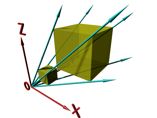
※ scale は、物体だけではなく、物体の位置も含めてスケーリングが行われる。原点以外の位置で scale を実行すると物体の位置も変わってしまうので注意する(図3.2-1)。
図3.2-1 スケールは物体とその位置に影響
例)scaleの記述
box{<0.5,0.5,0.5>,<1.5,1.5,1.5> scale 3}
この記述は下記と同等
box{<1.5,1.5,1.5>,<4.5,4.5,4.5>}
※ scale 3 は scale<3,3,3> と同等
∇ POV-Rayソース: 図3.2-1 スケールは物体とその位置に影響
//-------------------- Fig. 3.2-1 scale
#version 3.7
#include "colors.inc"
#include "textures.inc"
global_settings
{assumed_gamma 2.2}
camera{
location <7.5,-4,6>
sky<0,0,1>
right <-image_width/image_height,0,0>
look_at <2.5,3,2>
}
light_source {<-200,-300,1000> color White*0.5 }
light_source {<-300,-400,1000> color White*0.5 }
light_source {<-300,-500,1> color White*0.5 shadowless}
background{color White}
//====================================== axis
#declare S=4;
union{
cylinder{0,x*(S-0.5),0.05}
cone{x*(S-0.5),0.1,x*(S+0.1),0}
cylinder{0,y*(S+0.5),0.05}
cone{y*(S+0.5),0.1,y*(S+1.1),0}
cylinder{0,z*(S-0.5),0.05}
cone{z*(S-0.5),0.1,z*(S+0.1),0}
union{
text{ttf "cyrvetic.ttf","X",0.1,0
scale 1
rotate<90,0,0>
translate x*(S+0.2)
}
text{ttf "cyrvetic.ttf","Y",0.1,0
scale 1
rotate<90,0,0>
translate <-0.1,S+1.2,0>
}
text{ttf "cyrvetic.ttf","Z",0.1,0
scale 1
rotate<90,0,0>
translate <-0.12,0.12,S+0.2>
}
}
pigment{color rgb<1.0,0.2,0.2>}
finish{phong 1}
}
text{ttf "cyrvetic.ttf","O",0.1,0
pigment{Red}
finish{phong 1}
scale 1
rotate<90,0,0>
translate <-0.9,0,-0.5>
}
//========================================== box, arrow
#declare A=0.5;
#declare B=1.5;
#declare Scale=3;
box{A,B pigment{color rgb<1.0,1.0,0.2> filter 0.1}}
box{A,B pigment{color rgb<1.0,1.0,0.2> filter 0.3} scale Scale}
union{
cylinder{0,B*Scale+0.5,0.05}
cone{B*Scale+0.5,0.1,B*Scale+1.0,0}
cylinder{0, <B,A,A>*(Scale+0.5), 0.05}
cone{<B,A,A>*(Scale+0.5), 0.1, <B,A,A>*(Scale+1.0), 0}
cylinder{0, <A,B,A>*(Scale+0.5), 0.05}
cone{<A,B,A>*(Scale+0.5), 0.1, <A,B,A>*(Scale+1.0), 0}
cylinder{0, <A,A,B>*(Scale+0.5), 0.05}
cone{<A,A,B>*(Scale+0.5), 0.1, <A,A,B>*(Scale+1.0), 0}
cylinder{0, <A,B,B>*(Scale+0.5), 0.05}
cone{<A,B,B>*(Scale+0.5), 0.1, <A,B,B>*(Scale+1.0), 0}
cylinder{0, <B,A,B>*(Scale+0.5), 0.05}
cone{<B,A,B>*(Scale+0.5), 0.1, <B,A,B>*(Scale+1.0), 0}
cylinder{0, <B,B,A>*(Scale+0.5), 0.05}
cone{<B,B,A>*(Scale+0.5), 0.1, <B,B,A>*(Scale+1.0), 0}
pigment{color rgb<0.2,1.0,1.0>}
finish{phong 1}
}
3.2-2 回転(rotate)
rotate は物体やテクスチャなどの回転に使用する。
< rotate の構文 >
[ rotate <VECTOR> ]
rotate 回転のキーワード
<VECTOR>
設定対象の回転を行う。 回転は x 軸 → y 軸 → z 軸まわりの順に行われる。回転角度をベクトルで設定 [デフォルト:<0,0,0>]
※ 回転方向は▷「3.1 座標系」 を参照
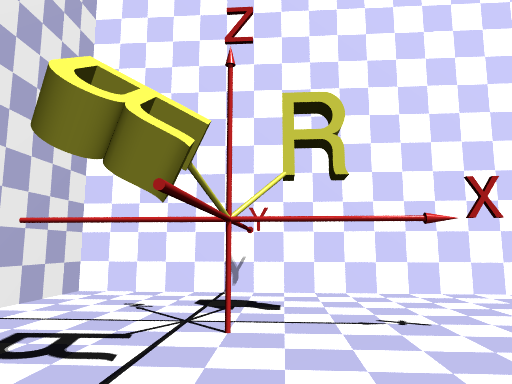
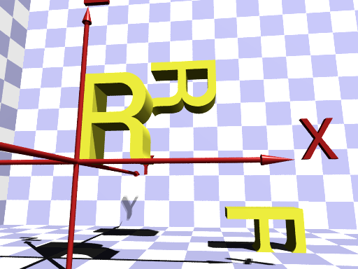
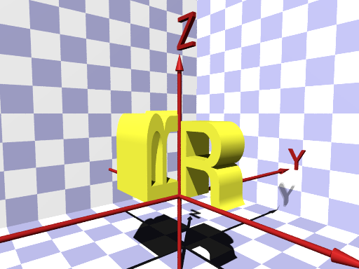
回転は常に軸まわりで行われるため、対象物が回転軸から離れていると結果の位置が予測しにくくなる。また通常回転は、( x 軸まわり)→( y 軸まわり)→( z 軸まわり)の順で行われるが、x、y、z が同じ角度であっても、回転する順序によって結果の位置が変わることもある。例えば、" Text_R " という物体を回転させる場合、
object {
Text_R
rotate <60,30,-90> // 最初に x軸まわりに60°、
// 次に y軸まわりに30°、
// 最後に z軸まわりに-90°回転
}
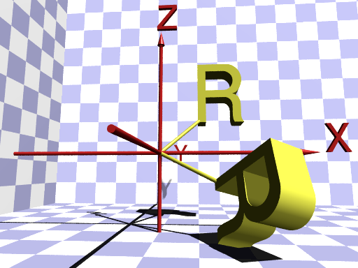
と、回転軸の順序が異なる
object {
Text_R
rotate z*-90 // 最初に z軸まわりに-90°回転
rotate y*30 // 次に y軸まわりに 30°回転
rotate x*60 // 最後に x軸まわりに 60°回転
}
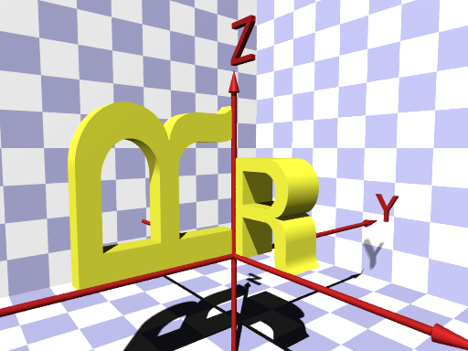
では下図のように結果の位置が異なる(両図とも奥のRが元の位置)。
(a) 回転 x → y → z
(b) 回転 z → y → x
図3.2-2 回転の順番による違い
以上のことから、複雑な回転を設定する場合は、対象物を原点に置いた後、物体をわかりやすい順序で、各軸ごとに分けて回転するとよい。
∇ POV-Rayソース: 図3.2-2 回転の順番による違い (a) 回転 x → y → z
//--------------- Fig. 3.2-2a rotation order
#version 3.7
#include "colors.inc"
#include "textures.inc"
global_settings
{assumed_gamma 2.2}
camera{
location <1,-7,-0.5>
sky<0,0,1>
right <-image_width/image_height,0,0>
look_at <0.5,0,0.5>
}
#declare X=500;
#declare Y=-500;
#declare Z=1000;
light_source {<X,Y,Z> color White*0.5}
light_source {<X,Y,Z> color White*0.5 scale 0.2}
light_source {<300,-600,-1> color White*0.5 shadowless}
background{color White}
#declare S=4;
//================================== floor, walls
union{
plane{x,-(S+2)}
plane{y,(S+2)}
plane{z,-2}
pigment{checker White*1.2, color rgb<0.8,0.8,1.0>}
finish{diffuse 1}
no_shadow
}
//================================== axis
union{
cylinder{-x*S,x*(S-0.5),0.05}
cone{x*(S-0.5),0.1,x*(S+0.1),0}
cylinder{-y*S,y*(S+0.5),0.05}
cone{y*(S+0.5),0.1,y*(S+1.1),0}
cylinder{-z*S,z*(S-1),0.05}
cone{z*(S-1),0.1,z*(S-0.6),0}
union{
text{ttf "cyrvetic.ttf","X",0.1,0
scale 1
rotate<90,0,0>
translate x*(S+0.2)
}
text{ttf "cyrvetic.ttf","Y",0.1,0
scale 1
rotate<90,0,0>
translate <-0.1,S+1.2,0>
}
text{ttf "cyrvetic.ttf","Z",0.1,0
scale 1
rotate<90,0,0>
translate <-0.12,0.12,S-0.5>
}
}
pigment{color rgb<1.0,0.2,0.2>}
finish{phong 1}
}
//================================ rotation
#declare R=
object{
union{
text{ttf "cyrvetic.ttf","R",0.3,0
scale 2.5
rotate x*90
translate y*0.3*2.5
translate 1}
cylinder{0,1.1,0.05}
pigment{color rgb<1.2,1.2,0.4>}
finish{phong 1}
}
}
object{R}
object{R rotate<60,30,-90>}
∇ POV-Rayソース: 図3.2-2 回転の順番による違い (b) 回転 z → y → x
//--------------- Fig. 3.2-2b rotation order
#version 3.7
#include "colors.inc"
#include "textures.inc"
global_settings
{assumed_gamma 2.2}
camera{
location <1,-7,-0.5>
sky<0,0,1>
right <-image_width/image_height,0,0>
look_at <0.5,0,0.5>
}
#declare X=500;
#declare Y=-500;
#declare Z=1000;
light_source {<X,Y,Z> color White*0.5}
light_source {<X,Y,Z> color White*0.5 scale 0.2}
light_source {<300,-600,-1> color White*0.5 shadowless}
background{color White}
#declare S=4;
//================================== floor, walls
union{
plane{x,-(S+2)}
plane{y,(S+2)}
plane{z,-2}
pigment{checker White*1.2, color rgb<0.8,0.8,1.0>}
finish{diffuse 1}
no_shadow
}
//================================== axis
union{
cylinder{-x*S,x*(S-0.5),0.05}
cone{x*(S-0.5),0.1,x*(S+0.1),0}
cylinder{-y*S,y*(S+0.5),0.05}
cone{y*(S+0.5),0.1,y*(S+1.1),0}
cylinder{-z*S,z*(S-1),0.05}
cone{z*(S-1),0.1,z*(S-0.6),0}
union{
text{ttf "cyrvetic.ttf","X",0.1,0
scale 1
rotate<90,0,0>
translate x*(S+0.2)
}
text{ttf "cyrvetic.ttf","Y",0.1,0
scale 1
rotate<90,0,0>
translate <-0.1,S+1.2,0>
}
text{ttf "cyrvetic.ttf","Z",0.1,0
scale 1
rotate<90,0,0>
translate <-0.12,0.12,S-0.5>
}
}
pigment{color rgb<1.0,0.2,0.2>}
finish{phong 1}
}
//================================ rotation
#declare R=
object{
union{
text{ttf "cyrvetic.ttf","R",0.3,0
scale 2.5
rotate x*90
translate y*0.3*2.5
translate 1}
cylinder{0,1.1,0.05}
pigment{color rgb<1.2,1.2,0.4>}
finish{phong 1}
}
}
object{R}
object{R rotate z*-90 rotate y*30 rotate x*60}
3.2-3 移動(translate)
translate は、物体やテクスチャの移動に使用する。相対移動距離で設定する。
< translate の構文 >
[ translate <VECTOR> ]
translate 移動のキーワード
<VECTOR>
設定対象の移動を行う。現在位置からの x、y、z 方向の移動距離をベクトルで設定 [デフォルト:<0,0,0>]
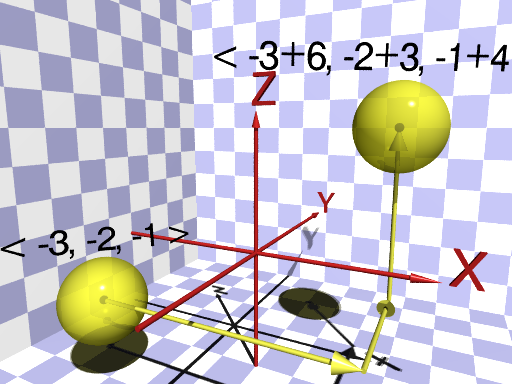
図3.2-3 物体の移動
例)上図の球の移動
sphere { <-3,-2,-1>, 1
pigment { White }
translate <6,3,4>
}
この場合、<-3,-2,-1>に置かれた球を translate <6, 3, 4> によって、<-3+6, -2+3, -1+4>つまり <3, 1, 3> に移動する。また、1つの軸方向だけに移動したいとき、下記のような記述もできる。
例)x方向だけの移動
sphere { <0,0,0>, 1
pigment { White }
translate x*6 // +x方向だけに6移動する。
}
∇ POV-Rayソース: 図3.2-3 物体の移動
//-------------------- Fig. 3.2-3 translate
#version 3.7
#include "colors.inc"
#include "textures.inc"
global_settings
{assumed_gamma 2.2}
camera{
location <4,-8,3>
sky<0,0,1>
right <-image_width/image_height,0,0>
look_at <0,0,1.5>
}
#declare X=500;
#declare Y=-500;
#declare Z=1000;
light_source {<X,Y,Z> color White*0.5}
light_source {<X,Y,Z> color White*0.5 scale 0.2}
light_source {<300,-600,-1> color White*0.5 shadowless}
background{color White}
#declare S=4;
//================================== floor, walls
union{
plane{x,-(S+2)}
plane{y,(S+2)}
plane{z,-3}
pigment{checker White*1.2, rgb<0.8,0.8,1.0>}
finish{diffuse 1}
no_shadow
}
//================================== axis
union{
cylinder{-x*S,x*(S-0.5),0.05}
cone{x*(S-0.5),0.1,x*(S+0.1),0}
cylinder{-y*S,y*(S+0.5),0.05}
cone{y*(S+0.5),0.1,y*(S+1.1),0}
cylinder{-z*S,z*(S-1),0.05}
cone{z*(S-1),0.1,z*(S-0.6),0}
union{
text{ttf "cyrvetic.ttf","X",0.1,0
scale 1
rotate<90,0,0>
translate x*(S+0.2)
}
text{ttf "cyrvetic.ttf","Y",0.1,0
scale 1
rotate<90,0,0>
translate <-0.1,S+1.2,0>
}
text{ttf "cyrvetic.ttf","Z",0.1,0
scale 1
rotate<90,0,0>
translate <-0.12,0.12,S-0.5>
}
}
pigment{color rgb<1.0,0.2,0.2>}
finish{phong 1}
}
//================================ translate
//----------------------original position
#declare X=-3;
#declare Y=-2;
#declare Z=-1;
//----------------------amount of translate
#declare Tx=6;
#declare Ty=3;
#declare Tz=4;
#declare Sphere=
object{
union{
sphere{0,0.1}
sphere{0,1
pigment{color rgb<1.2,1.2,0.4> filter 0.3}
finish{specular 1 roughness 0.001}
}
translate <X,Y,Z>
}
}
//======================== object translation
object{Sphere}
object{Sphere translate<Tx,Ty,Tz>}
union{
cylinder{<X,Y,Z>,<X+Tx-0.5,Y,Z>,0.05}
cone{0,0.2,x*0.5,0 translate<X+Tx-0.5,Y,Z>}
cylinder{<X+Tx,Y,Z>,<X+Tx,Y+Ty-0.5,Z>,0.05}
cone{0,0.2,y*0.5,0 translate<X+Tx,Y+Ty-0.5,Z>}
cylinder{<X+Tx,Y+Ty,Z>,<X+Tx,Y+Ty,Z+Tz-0.5>,0.05}
cone{0,0.2,z*0.5,0 translate<X+Tx,Y+Ty,Z+Tz-0.5>}
pigment{color rgb<1.2,1.2,0.4>}
finish{phong 1}
}
text{ttf "cyrvetic.ttf",
concat("< ",str(X,0,0),", ",str(Y,0,0),", ",
str(Z,0,0)," >"),0.01,x*-0.05
scale 0.8
translate x*-2
rotate<60,0,45>
translate <X,Y,Z+1.2>
no_shadow
}
text{ttf "cyrvetic.ttf",
concat("< ",str(X,0,0),"+",str(Tx,0,0),", ",
str(Y,0,0),"+",str(Ty,0,0),", ",
str(Z,0,0),"+",str(Tz,0,0)," >"),
0.01,x*-0.05
scale 0.8
translate x*-4
rotate<90,0,30>
translate <X+Tx,Y+Ty,Z+Tz+1.2>
no_shadow
}
3.2-4 行列(matrix)
matrixは、物体やテクスチャに変形行列を設定することによって、複雑な変形を一度に行うために使用する。
< matrix の構文 >
[ matrix <m00, m01, m02,
m10, m11, m12,
m20, m21, m22,
m30, m31, m32 > ]
matrix 変形行列のキーワード
m00~m32
4 x 4の行列式の各成分を実数で設定
matrix を使った場合、点 P : P=<px, py, pz> は次の式によって点 Q : Q=<qx, qy, qz> に変換される。
qx = m00 * px + m10 * py + m20 * pz + m30
qy = m01 * px + m11 * py + m21 * pz + m31
qz = m02 * px + m12 * py + m22 * pz + m32
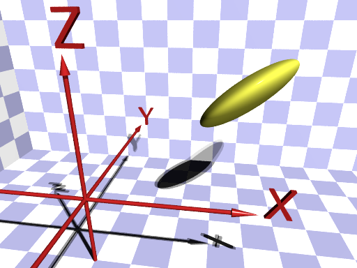
次の例の変形行列によって<2,1,2>に置かれた半径 1 の球が、図3.2-4(右)のように変形する。
例)球の行列による変形
object {
sphere{<2,1,2>,1
matrix <1, 1, 0,
0, 1, 0,
1, 0, 1,
0, 0, 0>
}
(a) 変形前
(b) 変形後
図3.2-4 変形行列(matrix)による変形
∇ POV-Rayソース: 図3.2-4 変形行列(matrix)による変形 (a) 変形前
//------------- Fig. 3.2-4a no matrix
#version 3.7
#include "colors.inc"
#include "textures.inc"
global_settings
{assumed_gamma 2.2}
camera{
location <3,-5,4>
sky<0,0,1>
right <-image_width/image_height,0,0>
look_at <2,2,1>
}
#declare X=500;
#declare Y=-500;
#declare Z=1000;
light_source {<X,Y,Z> color White*0.5}
light_source {<X,Y,Z> color White*0.5 rotate 1}
light_source {<300,-600,-1> color White*0.5 shadowless}
background{color White}
#declare S=4;
//================================== floor, walls
union{
plane{x,-(S+2)}
plane{y,(S+2)}
plane{z,-2}
pigment{checker White*1.2, color rgb<0.8,0.8,1.0>}
finish{diffuse 1}
no_shadow
}
//================================== axis
union{
cylinder{-x*S,x*(S-0.5),0.05}
cone{x*(S-0.5),0.1,x*(S+0.1),0}
cylinder{-y*S,y*(S+0.5),0.05}
cone{y*(S+0.5),0.1,y*(S+1.1),0}
cylinder{-z*S,z*(S-1),0.05}
cone{z*(S-1),0.1,z*(S-0.6),0}
union{
text{ttf "cyrvetic.ttf","X",0.1,0
scale 1
rotate<90,0,0>
translate x*(S+0.2)
}
text{ttf "cyrvetic.ttf","Y",0.1,0
scale 1
rotate<90,0,0>
translate <-0.1,S+1.2,0>
}
text{ttf "cyrvetic.ttf","Z",0.1,0
scale 1
rotate<90,0,0>
translate <-0.12,0.12,S-0.5>
}
}
pigment{color rgb<1.0,0.2,0.2>}
finish{phong 1}
}
//=============================== No matrix
#declare Sphere=
object{
sphere{<2,1,2>,1
pigment{color rgb<1.2,1.2,0.4> filter 0.0}
finish{specular 1 roughness 0.001}
}
}
object{Sphere}
∇ POV-Rayソース: 図3.2-4 変形行列(matrix)による変形 (b) 変形後
//------------- Fig. 3.2-4b matrix
#version 3.7
#include "colors.inc"
#include "textures.inc"
global_settings
{assumed_gamma 2.2}
camera{
location <3,-5,4>
sky<0,0,1>
right <-image_width/image_height,0,0>
look_at <2,2,1>
}
#declare X=500;
#declare Y=-500;
#declare Z=1000;
light_source {<X,Y,Z> color White*0.5}
light_source {<X,Y,Z> color White*0.5 rotate 1}
light_source {<300,-600,-1> color White*0.5 shadowless}
background{color White}
#declare S=4;
//================================== floor, walls
union{
plane{x,-(S+2)}
plane{y,(S+2)}
plane{z,-2}
pigment{checker White*1.2, color rgb<0.8,0.8,1.0> }
finish{diffuse 1}
no_shadow
}
//================================== axis
union{
cylinder{-x*S,x*(S-0.5),0.05}
cone{x*(S-0.5),0.1,x*(S+0.1),0}
cylinder{-y*S,y*(S+0.5),0.05}
cone{y*(S+0.5),0.1,y*(S+1.1),0}
cylinder{-z*S,z*(S-1),0.05}
cone{z*(S-1),0.1,z*(S-0.6),0}
union{
text{ttf "cyrvetic.ttf","X",0.1,0
scale 1
rotate<90,0,0>
translate x*(S+0.2)
}
text{ttf "cyrvetic.ttf","Y",0.1,0
scale 1
rotate<90,0,0>
translate <-0.1,S+1.2,0>
}
text{ttf "cyrvetic.ttf","Z",0.1,0
scale 1
rotate<90,0,0>
translate <-0.12,0.12,S-0.5>
}
}
pigment{color rgb<1.0,0.2,0.2>}
finish{phong 1}
}
//============================== matrix
#declare Sphere=
object{
sphere{<2,1,2>,1
pigment{color rgb<1.2,1.2,0.4> filter 0.0}
finish{specular 1 roughness 0.001}
}
}
#declare Matrix=
transform{
matrix < 1, 1, 0,
0, 1, 0,
1, 0, 1,
0, 0, 0 >
}
object{Sphere transform Matrix}
3.3 変形の順序
複数の変形(スケーリング、回転、移動)を組みあわせる場合は変形の順序に気をつける。対象物は各軸まわりで回転し、原点からの距離に比例してスケーリングされるため、順序を間違えると全く予期しない位置に移動してしまうことがある。
物体の変形を行う場合は、一般的には
(1) 物体を原点<0,0,0>に置く
の順で行うとエラーが少なくなる。
特に rotate と translate、または scale と taranslate を組みあわせる場合は注意する。以下にそれぞれ例を示す。
《 rotate と translate の場合》
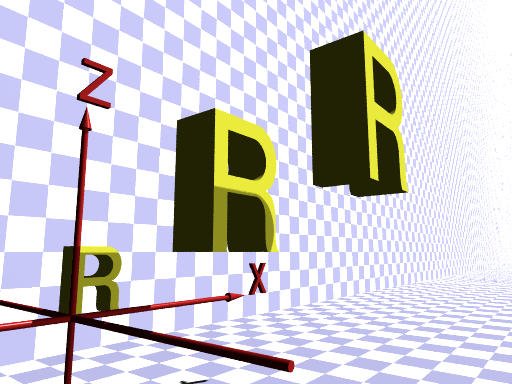
手前左:元の位置、右下奥:例1の結果の位置、中央奥:例2の結果の位置
図3.3a rotate と translate の順序による違い
∇ POV-Rayソース: 図3.3a rotate と translate の順序による違い
//----------- Fig. 3.3a rotate <-> translate
#version 3.7
#include "colors.inc"
#include "textures.inc"
global_settings
{assumed_gamma 2.2}
camera{
location <2.5,-5,-0.5>
sky<0,0,1>
right <-image_width/image_height,0,0>
look_at <2,0,0.5>
}
#declare X=500;
#declare Y=-500;
#declare Z=1000;
light_source {<X,Y,Z> color White*0.5}
light_source {<X,Y,Z> color White*0.5 scale 0.2}
light_source {<300,-600,-1> color White*0.5 shadowless}
background{color White}
#declare S=4;
//================================== floor, walls
union{
plane{x,-(S+2)}
plane{y,(S+2)}
plane{z,-2}
pigment{checker White*1.2, color rgb<0.8,0.8,1.0>}
finish{diffuse 1}
no_shadow
}
//================================== axis
union{
cylinder{-x*S,x*(S-0.5),0.05}
cone{x*(S-0.5),0.1,x*(S+0.1),0}
cylinder{-y*S,y*(S+0.5),0.05}
cone{y*(S+0.5),0.1,y*(S+1.1),0}
cylinder{-z*S,z*(S-1),0.05}
cone{z*(S-1),0.1,z*(S-0.6),0}
union{
text{ttf "cyrvetic.ttf","X",0.1,0
scale 1
rotate<90,0,0>
translate x*(S+0.2)
}
text{ttf "cyrvetic.ttf","Y",0.1,0
scale 1
rotate<90,0,0>
translate <-0.1,S+1.2,0>
}
text{ttf "cyrvetic.ttf","Z",0.1,0
scale 1
rotate<90,0,0>
translate <-0.12,0.12,S-0.5>
}
}
pigment{color rgb<1.0,0.2,0.2>}
finish{phong 1}
}
//=================== rotate <-> translate
#declare R=
object{
text{ttf "cyrvetic.ttf","R",0.3,0
pigment{color rgb<1.5,1.5,0.4>}
finish{phong 1}
scale 2.5
rotate x*90
translate y*0.3*2.5
}
}
object{R}
object{R rotate y*90 translate<1,2,3>}
object{R translate<1,2,3> rotate y*90}
原点に置かれた Text_R という物体(図3.3aの左手前)を、y 軸まわりに90°回転させて座標<1,2,3>に移動させる場合、回転と移動の順番が異なると結果も違ってくる。
例)移動して回転
object{Text_R
translate<1,2,3> // 最初に移動
rotate y*90 // 次に回転
}
これでは上図のように全く違う位置に移動してしまう(上図の右下で床に埋まっているR)。正しい設定は次の例である。
例)回転して移動
object{Text_R
rotate y*90 // 最初に回転
translate<1,2,3> // 次に移動
}
《 scale と translate の場合》
原点に置かれた Text_R という物体(図3.3b の左下)を、2倍に拡大して座標<1,-2,1>に移動させる場合、拡大と移動の順番が異なると結果も違ってくる。
左下:元の位置、中央:例2の結果の位置、右上:例1の結果の位置
図3.3b scale と translate の順序による違い
∇ POV-Rayソース: 図3.3b scale と translate の順序による違い
//------------ Fig. 3.3b scale <-> translate
#version 3.7
#include "colors.inc"
#include "textures.inc"
global_settings
{assumed_gamma 2.2}
camera{
location <-3,-6,1>
sky<0,0,1>
right <-image_width/image_height,0,0>
look_at <2,-2,2>
}
#declare X=500;
#declare Y=-500;
#declare Z=1000;
light_source {<X,Y,Z> color White*0.5}
light_source {<X,Y,Z> color White*0.5 scale 0.2}
light_source {<300,-600,-1> color White*0.5 shadowless}
background{color White}
#declare S=4;
//================================== floor, walls
union{
plane{x,-(S+2)}
plane{y,(S+2)}
plane{z,-2}
pigment{checker White*1.2, color rgb<0.8,0.8,1.0>}
finish{diffuse 1}
no_shadow
}
//================================== axis
union{
cylinder{-x*S,x*(S-0.5),0.05}
cone{x*(S-0.5),0.1,x*(S+0.1),0}
cylinder{-y*S,y*(S+0.5),0.05}
cone{y*(S+0.5),0.1,y*(S+1.1),0}
cylinder{-z*S,z*(S-1),0.05}
cone{z*(S-1),0.1,z*(S-0.6),0}
union{
text{ttf "cyrvetic.ttf","X",0.1,0
scale 1
rotate<90,0,0>
translate x*(S+0.2)
}
text{ttf "cyrvetic.ttf","Y",0.1,0
scale 1
rotate<90,0,0>
translate <-0.1,S+1.2,0>
}
text{ttf "cyrvetic.ttf","Z",0.1,0
scale 1
rotate<90,0,0>
translate <-0.12,0.12,S-0.5>
}
}
pigment{color rgb<1.0,0.2,0.2>}
finish{phong 1}
}
//===================== scale <-> translate
#declare R=
text{ttf "cyrvetic.ttf","R",0.3,0
pigment{color rgb<1.5,1.5,0.4>}
finish{phong 1}
scale 1.5
rotate x*90
translate y*0.3*1.5
}
#declare Scl=2;
#declare T=<1,-2,1>;
object{R}
object{R translate T scale Scl}
object{R scale Scl translate T}
例)移動して拡大
object{Text_R
translate <1,-2,1> // 最初に移動
scale 2
}
スケールは対象物の原点からの距離に比例するため、translate <1,-2,1>に比例して物体を拡大し、上図のように別の位置に移動させてしまう(上図の右上のR)。正しい設定は次の例である。
例)拡大して移動
object{Text_R
scale 2 // 最初に拡大
translate<1,-2,1>
}
《 scale と rotate の場合》
対象物が原点にあればスケールと回転の順序によってその位置が変わることはないが、次の例のように不均一なスケールを行う場合は、その順序によって形状が変化する。
例)拡大して回転
object{Text_R
scale <2,0.5,1.5> // 最初にスケール
rotate <90,-90,0>
}
例)回転して拡大
object{Text_R
rotate <90,-90,0> // 最初に回転
scale <2,0.5,1.5>
}
(a) scale → rotate
(b) rotate → scale
図3.3c rotate と scale の順序による違い
∇ POV-Rayソース: 図3.3c rotate と scale の順序による違い (a) scale → rotate
//------------ Fig. 3.3c-a
#version 3.7
#include "colors.inc"
#include "textures.inc"
global_settings
{assumed_gamma 2.2}
camera{
location <5,-4,2>
sky<0,0,1>
right <-image_width/image_height,0,0>
look_at <0,0,1.5>
}
#declare X=500;
#declare Y=-500;
#declare Z=1000;
light_source {<X,Y,Z> color White*0.5}
light_source {<X,Y,Z> color White*0.5 scale 0.2}
light_source {<300,-600,-1> color White*0.5 shadowless}
background{color White}
#declare S=4;
//================================== floor, walls
union{
plane{x,-(S+2)}
plane{y,(S+2)}
plane{z,-2}
pigment{checker White*1.2, color rgb<0.8,0.8,1.0>}
finish{diffuse 1}
no_shadow
}
//================================== axis
union{
cylinder{-x*S,x*(S-0.5),0.05}
cone{x*(S-0.5),0.1,x*(S+0.1),0}
cylinder{-y*S,y*(S+0.5),0.05}
cone{y*(S+0.5),0.1,y*(S+1.1),0}
cylinder{-z*S,z*(S-1),0.05}
cone{z*(S-1),0.1,z*(S-0.6),0}
union{
text{ttf "cyrvetic.ttf","X",0.1,0
scale 1
rotate<90,0,0>
translate x*(S+0.2)
}
text{ttf "cyrvetic.ttf","Y",0.1,0
scale 1
rotate<90,0,0>
translate <-0.1,S+1.2,0>
}
text{ttf "cyrvetic.ttf","Z",0.1,0
scale 1
rotate<90,0,0>
translate <-0.12,0.12,S-0.5>
}
}
pigment{color rgb<1.0,0.2,0.2>}
finish{phong 1}
}
//======================= scale -> rotate
#declare R=
text{ttf "cyrvetic.ttf","R",0.3,0
pigment{color rgb<1.5,1.5,0.4>}
finish{phong 1}
scale 2.5
rotate x*90
translate y*0.3*2.5
}
#declare Scl=<2,0.5,1.5>;
#declare T=<90,-90,0>;
object{R}
object{R scale Scl rotate T}
∇ POV-Rayソース: 図3.3c rotate と scale の順序による違い (b) rotate → scale
//------------ Fig. 3.3c-b
#version 3.7
#include "colors.inc"
#include "textures.inc"
global_settings
{assumed_gamma 2.2}
camera{
location <5,-4,2>
sky<0,0,1>
right <-image_width/image_height,0,0>
look_at <0,0,1.5>
}
#declare X=500;
#declare Y=-500;
#declare Z=1000;
light_source {<X,Y,Z> color White*0.5}
light_source {<X,Y,Z> color White*0.5 scale 0.2}
light_source {<300,-600,-1> color White*0.5 shadowless}
background{color White}
#declare S=4;
//================================== floor, walls
union{
plane{x,-(S+2)}
plane{y,(S+2)}
plane{z,-2}
pigment{checker White*1.2, color rgb<0.8,0.8,1.0>}
finish{diffuse 1}
no_shadow
}
//================================== axis
union{
cylinder{-x*S,x*(S-0.5),0.05}
cone{x*(S-0.5),0.1,x*(S+0.1),0}
cylinder{-y*S,y*(S+0.5),0.05}
cone{y*(S+0.5),0.1,y*(S+1.1),0}
cylinder{-z*S,z*(S-1),0.05}
cone{z*(S-1),0.1,z*(S-0.6),0}
union{
text{ttf "cyrvetic.ttf","X",0.1,0
scale 1
rotate<90,0,0>
translate x*(S+0.2)
}
text{ttf "cyrvetic.ttf","Y",0.1,0
scale 1
rotate<90,0,0>
translate <-0.1,S+1.2,0>
}
text{ttf "cyrvetic.ttf","Z",0.1,0
scale 1
rotate<90,0,0>
translate <-0.12,0.12,S-0.5>
}
}
pigment{color rgb<1.0,0.2,0.2>}
finish{phong 1}
}
//------------------------------ rotate -> scale
#declare R=
text{ttf "cyrvetic.ttf","R",0.3,0
pigment{color rgb<1.5,1.5,0.4>}
finish{phong 1}
scale 2.5
rotate x*90
translate y*0.3*2.5
}
#declare Scl=<2,0.5,1.5>;
#declare T=<90,-90,0>;
object{R}
object{R rotate T scale Scl}
3.4 変形識別子 transform
変形識別子を使ってシーンファイルを読みやすくできる。また、宣言の変形パラメータを変更すると、その宣言が使われている部分を一斉に変えることができる。
この識別子は次のように transform のキーワードを使って宣言する。
#declare IDENTIFIER = transform { TRANSFORMATION... }
IDENTIFIER は 40文字以下の名前であり、TRANSFORMATION... は1つ以上のtranslate、rotate、scale、matrix、または前に宣言された変形識別子である。
変形識別子の呼び出しは、キーワード transform の後に識別子を記述する(括弧で囲む必要はない)。
例)変形識別子の記述
#declare MyTrans = transform{rotate x*90 scale 1.5 translate <0,2,3>}
object {
MyObject // 物体識別子MyObject
transform MyTrans // 変形 MyTrans の適用
}
3.5 テクスチャと物体のスケーリング
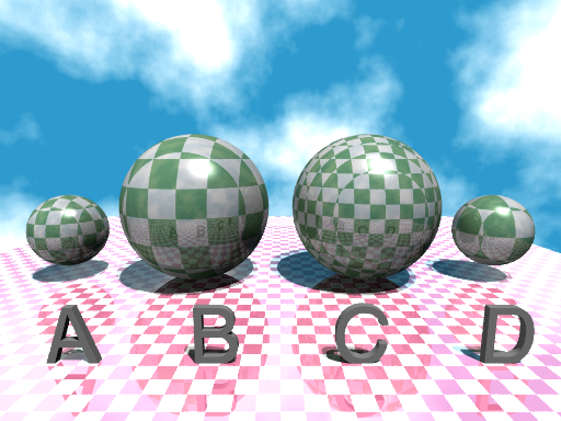
テクスチャを貼り付けた物体を変形させると、そのテクスチャは物体の形状と一緒に変形する。しかし、テクスチャを貼り付ける前に物体を変形させると、そのテクスチャは変形せず物体の形状だけが変形する。また、テクスチャ文の中で変形を行った場合はテクスチャだけが変形し、物体そのものは変形しない。
A 元の球、B 球全体の拡大、C 球形だけ拡大、D テクスチャだけ拡大
図3.5 サイズとテクスチャのスケーリング
∇ POV-Rayソース: 図3.5 サイズとテクスチャのスケーリング
//-------------------- Fig. 3.5
#version 3.7
#include "colors.inc"
#include "textures.inc"
global_settings
{assumed_gamma 2.2}
camera{
location<0,-14,5>
sky<0,0,1>
right <-image_width/image_height,0,0>
look_at < 0, -1, 3 >
angle 80
}
light_source {<200,-300,1000> color White*0.5 }
light_source {<300,-400,1000> color White*0.5 }
light_source {<-300,-300,1> color White*0.5 shadowless}
//--------------------------checker pattern
#declare Check =
texture{
pigment{checker White, color rgb<0.5,0.7,0.5> scale 0.5}
finish{phong 1 reflection 0.1}
}
//============================ original object
sphere{0,1.5
texture{Check}
translate <-9,0,2>
}
//================ scale 2 : checker & sphere
sphere{0,1.5
texture{Check}
scale 2
translate <-3.5,0,3>
}
//================ scale 2 : sphere
sphere{0,1.5
scale 2
texture{Check}
translate <3.5,0,3>
}
//================ scale 2 : checker
sphere{0,1.5
texture{Check scale 2}
translate <9,0,2>
}
//-------------------------------text
text{ttf "cyrvetic.ttf","A B C D",0.1,0
scale 2
pigment{White*0.8}
rotate<90,0,0>
translate <-5.8,-6.2,0>
}
//---------------------------------ground
plane{z,0 clipped_by{box{-15,15}}
pigment{checker MediumVioletRed, White*1.2 scale 0.5}
finish{diffuse 1 reflection 0.4}
}
//------------------------------------sky
sky_sphere{
pigment{
wrinkles
color_map{
[0.3 White*1.2]
// [0.7 color rgb<0.3,0.3,1.0>]
[0.7 color SkyBlue]
}
scale 0.3
}
}
スケーリング(scale)はカラーパターンとノーマルパターンに個別に設定できる。
※ ノーマルパターンをスケーリングする場合は、凹凸の広さと間隔にしか影響しない(見 かけ上の凹凸の程度は変化しない)。▷「12.2 ノーマル」 参照
例)いろいろなscale
box { <0, 0, 0>, <1, 1, 1>
texture {
pigment {
checker Red, White
scale 0.25 // カラーパターンだけをスケールする。
}
normal {
bumps 0.3 // 見かけの凹凸の高さの設定。
scale 0.2 // 凹凸の直径と間隔だけをスケールする(高さとカラーパ
} // ターンには全く影響しない)。
rotate y*45 // テクスチャ全体を回転させる(物体そのものは回転しない)。
}
}
(End) 3.座標系と変形