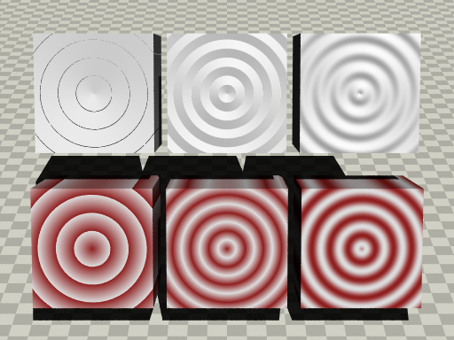
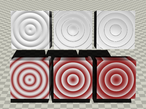
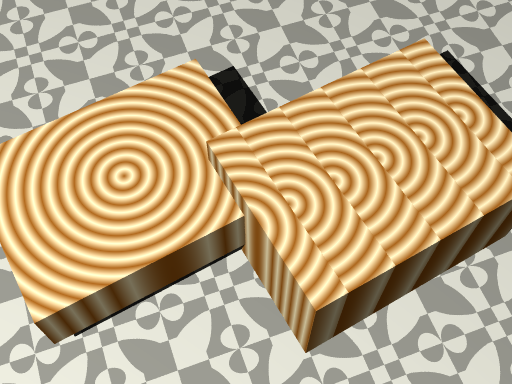
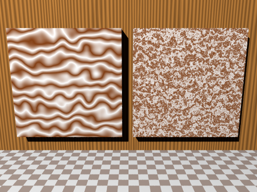
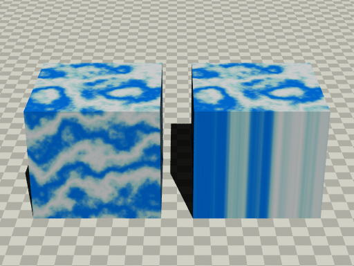
ramp_wave | triangle_wave | sine_wave
(上段)ノーマルで使用
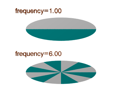
図13.2-3a 波形タイプ(その1)
scallop_wave | cubic_wave | poly_wave
(上段)ノーマルで使用
図13.2-3b 波形タイプ(その2)
∇ POV-Rayソース: 図13.2-3a 波形タイプ(その1)
//-------------------- Fig. 13.2-3a /wave-forms/ 1
#version 3.7
#include "colors.inc"
#include "textures.inc"
global_settings
{ assumed_gamma 2.2 }
//--------------------------my wood
#declare My_wood_p=
pigment{
wood
color_map{[0 Brown][1 White]}
scale 0.3
}
#declare My_wood_n=
normal{
wood 1
scale 0.3
}
//--------- wood pattern (box)
//============================ ramp_wave
box{-1,1 pigment{White}
normal{My_wood_n ramp_wave} // <<<---normal
scale 0.9 rotate x*70
translate <-2,1.2,2>}
box{-1,1
pigment{My_wood_p ramp_wave} // <<<---pigment
scale 0.9 rotate x*70
translate <-2,0,0> }
//============================ triangle_wave
box{-1,1 pigment{White}
normal{My_wood_n triangle_wave} // <<<---normal
scale 0.9 rotate x*70
translate <0,1.2,2>}
box{-1,1
pigment{My_wood_p triangle_wave} // <<<---pigment
scale 0.9 rotate x*70
translate <0,0,0> }
//============================ sine_wave
box{-1,1 pigment{White}
normal{My_wood_n sine_wave} // <<<---normal
scale 0.9 rotate x*70
translate <2,1.2,2>}
box{-1,1
pigment{My_wood_p sine_wave} // <<<---pigment
scale 0.9 rotate x*70
translate <2,0,0> }
//------------------------ camera and light
camera{
location <0,-14,8>
sky <0, 0, 1>
right <-image_width/image_height,0,0>
look_at <0, 0, 1.2>
angle 25
}
light_source{ <100, -400, 500> color rgb 1.5}
//---------------------------------floor
#declare CA1=rgb<0.85,0.85,0.8>;
#declare CA2=rgb<0.85,0.85,0.8>*1.2;
plane{ z, -1.01
pigment{ checker color CA1, color CA2 scale 0.3 }
}
∇ POV-Rayソース: 図13.2-3b 波形タイプ(その2)
//-------------------- Fig. 13.2-3b /wave-forms/ 2
#version 3.7
#include "colors.inc"
#include "textures.inc"
global_settings
{ assumed_gamma 2.2 }
//--------------------------my wood
#declare My_wood_p =
pigment{
wood
color_map{[0 Brown][1 White]}
scale 0.3
}
#declare My_wood_n =
normal{
wood 1
scale 0.3
}
//--------- wood pattern (box)
//============================ scallop_wave
box{-1,1 pigment{White}
normal{My_wood_n scallop_wave} // <<<---normal
scale 0.9 rotate x*70
translate <-2,1.2,2>}
box{-1,1
pigment{My_wood_p scallop_wave} // <<<---pigment
scale 0.9 rotate x*70
translate <-2,0,0> }
//============================ cubic_wave
box{-1,1 pigment{White}
normal{My_wood_n cubic_wave} // <<<---normal
scale 0.9 rotate x*70
translate <0,1.2,2>}
box{-1,1
pigment{My_wood_p cubic_wave} // <<<---pigment
scale 0.9 rotate x*70
translate <0,0,0> }
//============================ poly_wave
box{-1,1 pigment{White}
normal{My_wood_n poly_wave 2} // <<<---normal
scale 0.9 rotate x*70
translate <2,1.2,2>}
box{-1,1
pigment{My_wood_p poly_wave 2} // <<<---pigment
scale 0.9 rotate x*70
translate <2,0,0> }
//------------------------ camera and light
camera{
location <0,-14,8>
sky <0, 0, 1>
right <-image_width/image_height,0,0>
look_at <0, 0, 1.2>
angle 25
}
light_source{ <100, -400, 500> color rgb 1.5}
//---------------------------------floor
#declare CA1=rgb<0.85,0.85,0.8>;
#declare CA2=rgb<0.85,0.85,0.8>*1.2;
plane{ z, -1.01
pigment{ checker color CA1, color CA2 scale 0.3 }
}
主な波形の特徴
ramp_wave
傾斜路のような直線的変化でジグザグがある波(デフォルト)
triangle_wave
三角波で直線的な変化をする波
sine_wave
sin波で滑らかに変化する波
scallop_wave
sine_wave の絶対値を使用した波
cubic_wave
立方体の角を滑らかにしたような波
poly_wave
poly_wave VAL のように使用。VALは指数で、2.0 ではゆるやかに開始して最後に急激に上昇、デフォルトは 1.0で ramp_wave と同じ。
※ 注意 波形の設定が効果のないもの
13.2-4 ワープ(warp)
ワープは、設定された一連の手順に従って対象物体のテクスチャに影響を与える。従来、このようなテクスチャへ影響を与える代表的なものとして乱れ(turbulence)があった。POV-Rayではテクスチャへ影響する実行順序は、この乱れの作用が一番最初となっていて、多様な表現の制限になっていた。このような手続きの順番などをコントロールするためにワープが作られた。ワープ(warp)文は必要に応じて、複数記述できる。
ワープには大きく4つに分類できる。▷ (a) black_hole ブラックホール ▷ (b) repeat 繰り返し ▷ (c) turbulence 乱れ ▷ (d) マッピング (cylindrical 、spherical 、toroidal 、planar 、cubic )
< warp 全体の構文 >
pigment {
warp {
black_hole LOCATION, RADIUS [BLACK_HOLE_...] |
repeat [DIRECTION] [REPEAT_ITEMS...] |
turbulence [AMOUNT] [TURB_ITEMS...] |
cylindrical [ orientation <VECTOR> | dist_exp FLOAT ] |
spherical [ orientation <VECTOR> | dist_exp FLOAT ] |
toroidal [ orientation <VECTOR> | dist_exp FLOAT |
major_radius FLOAT ] |
planar [ <VECTOR> , FLOAT ] |
cubic |
}
}
pigment ピグメントのキーワード
warp ワープのキーワード
black_hole ブラックホールのキーワード ▷「 (a) black_hole」 参照
repeat 繰り返しのキーワード ▷ 「(b) repeat」 参照
turbulence 乱れ(乱流)のキーワード ▷「 (c) turbulence」 参照
cylindrical 円柱マッピングのキーワード ▷「 (d1) cylindrical」 参照
spherical 球マッピングのキーワード ▷「 (d2) spherical」 参照
toroidal ドーナツマッピングのキーワード ▷「 (d3) toroidal」 参照
planar 平面マッピングのキーワード ▷「 (d4) planar」 参照
cubic 立方体マッピングのキーワード ▷「 (d5) cubic」 参照
(a) ブラックホール(black_hole)
名前のとおり、周辺のものを吸い込むイメージのような効果がある。black_hole を設定することで、パターンを部分的に歪めることができる。以下にブラックホール文について示す。
< warp - black_hole の構文 >
pigment {
warp {
black_hole <LOCATION>, RADIUS
[ strength STRENGTH ]
[ falloff AMOUNT ]
[ inverse ]
[ repeat <REPEAT> ]
[ turbulence <AMOUNT> ]
}
}
pigment ピグメントのキーワード
warp ワープのキーワード
black_hole ブラックホールのキーワード
<LOCATION>
ブラックホールの x,y,z 位置(ベクトル)
RADIUS
周囲に影響を与える半径、数値
strength STRENGTH影響の強さ [デフォルト:1.0 ]
falloff AMOUNT影響が減衰の強さ [デフォルト:2.0 ]
inverse 中心から押し出される(中心に引き込まれるの反対)
repeat <REPEAT> x,y,z の距離で繰り返す。[デフォルト:<0,0,0>]
turbulence <AMOUNT>repeat のランダム性、x,y,z 軸のランダム距離の最大値 [デフォルト:<0,0,0>]
※ 注意
(a1) black_hole の効果
次の図13.2-4 (a1) に、wood パターンに black_hole を適用した例を示す。この図は、左側が通常の場合、右側が black_hole により年輪が部分的に歪められている。
(左側)通常の wood
図13.2-4 (a1) black_hole(ブラックホール)
∇ POV-Rayソース: 図13.2-4 (a1) black_hole(ブラックホール)
//-------------------- Fig. 13.2-4a1 black_hole
#version 3.7
#include "colors.inc"
#include "textures.inc"
global_settings
{ assumed_gamma 2.2 }
camera {
location <0, -10,20>
sky <0, 0, 1>
right <-image_width/image_height,0,0>
look_at <0,1,0.2>
angle 43
}
light_source { <-20, -30, 50> rgb 1.2 }
//---------------------color map define
#declare WMAP=
color_map {
[0.0 color rgb<1,0.6,0.2>]
[1.0 color rgb<0.8,0.75,0.6>*2]
}
//=============== left-box
box{-1,1 scale <4,3,1>
pigment {
wood
rotate x*0
scale 0.5
color_map{WMAP}
}
rotate z*30
translate <-4,0,2>
}
//================ right-box ==== black_hole (warp)
box{-1,1 scale <4,3,2>
pigment {
wood
rotate x*0
scale 0.5
color_map{WMAP}
warp{
black_hole <-2.4,0,2>,2.5 // <<<----black_hole
}
}
rotate z*30
translate <3.5,0,2>
}
//---------------------------------floor
#declare CA1=rgb<0.85,0.85,0.8>;
#declare CA2=rgb<0.85,0.85,0.8>*1.5;
plane{z,0
pigment {checker CA1 CA2 rotate x*90 scale 1
warp{black_hole <0, 0, 0> 2 strength 1.8
falloff 1.1 repeat <4,4,0>
}
rotate z*20
}
}
(a2) black_hole / reperat 使用
次の図13.2-4 (a2) は、床面である x-y 平面にパターン cheker を設定し、black_holede でパターンに歪みを与え、repeat を使って warp を規則的に繰り返し適用した例である。
図13.2-4 (a2) black_hole / reperat
∇ POV-Rayソース: 図13.2-4 (a2) black_hole / reperat
//----------- Fig. 13.2-4a2 black_hole/repeat
#version 3.7
#include "colors.inc"
#include "textures.inc"
#include "stones.inc"
global_settings
{ assumed_gamma 2.2 }
camera{
location <0,-40,20>
sky <0, 0, 1>
right <-image_width/image_height,0,0>
look_at <0, 0, 0>
angle 17
}
light_source{ <-120, -200, 300> color rgb 1.7}
//================================ black_hole (floor)
#declare CA1=rgb<0.5,0.85,0.4>*0.5;
#declare CA2=rgb<1,0.9,0.7>*1.;
plane{ z, 0
pigment{
checker CA1 CA2 scale 0.3
warp {
black_hole <0.0, 2.0, 0.0>,1
strength 2
repeat <3,3,0> // <<<---black hole ----repeat
}
}
}
//---------------------------wall and desk
#declare AA=
difference {
cylinder { z*-1, z*8 , 8
pigment{ White }
}
cylinder { z*-1, z*9, 6
texture { T_Grnt2 scale 2 } }
}
difference {
object {AA}
box {0,20
texture { T_Grnt2 scale 2 }
translate <-10,-20,0>
}
}
box{ 0,1 scale <5,3,0.5>
texture {T_Grnt16 scale 2
}
translate <-3,-1,0>
}
(a3) black_hole / repeat (turbulence) 使用
次の図13.2-4 (a3) は、床面である x-y 平面にパターン cheker を設定し、black_holede でパターンに歪みを与え、repeat を使って warp を繰り返すときに、turbulence により乱れを生じさせた例である。
図13.2-4 (a3) black_hole / repeat (turbulence)
∇ POV-Rayソース: 図13.2-4 (a3) black_hole / repeat (turbulence)
//----------- Fig. 13.2-4a3 black_hole/repeat-tu
#version 3.7
#include "colors.inc"
#include "textures.inc"
#include "stones.inc"
global_settings
{ assumed_gamma 2.2 }
camera{
location <0,-40,20>
sky <0, 0, 1>
right <-image_width/image_height,0,0>
look_at <0, 0, 0>
angle 17
}
light_source{ <-120, -200, 300> color rgb 1.7}
//================================ black_hole (floor)
#declare CA1=rgb<0.5,0.85,0.4>*0.5;
#declare CA2=rgb<1,0.9,0.7>*1.;
plane{ z, 0
pigment{
checker CA1 CA2 scale 0.3
warp {
black_hole <0.0, 2.0, 0.0>,1
strength 2
repeat <3,3,0> // <<<---black hole ----repeat
turbulence <1.2,0.5,0> // <<<------turbulence
}
}
}
//---------------------------wall and desk
#declare AA=
difference {
cylinder { z*-1, z*8 , 8
pigment{ White }
}
cylinder { z*-1, z*9, 6
texture { T_Grnt2 scale 2 } }
}
difference {
object {AA}
box {0,20
texture { T_Grnt2 scale 2 }
translate <-10,-20,0>
}
}
box{ 0,1 scale <5,3,0.5>
texture {T_Grnt16 scale 2
}
translate <-3,-1,0>
}
(b) 繰り返し(repeat)
パターンの繰り返しを指示する。繰り返しの方向や距離などを与える。
< warp - repeat の構文 >
pigment {
warp {
repeat <DIRECTION>
[ offset <AMOUNT> ]
[ flip <AXIS> ]
}
}
pigment ピグメントのキーワード
warp ワープのキーワード
repeat 繰り返しのキーワード
<DIRECTION>
繰り返し距離 x,y,z 値から1つ設定、残り2値は 0 を記述
offset <AMOUNT>ずらすときの移動距離 x,y,z [デフォルト:<0,0,0>]
flip <AXIS>各軸の反転スイッチ、反転1 [デフォルト:<0,0,0>]
(b1) repeat の効果
次の図13.2-4 (b1)の右側は、wood パターンを設定し、repeat を使って x 方向にパターンを繰り返した例である。
(左側)通常の wood
図13.2-4 (b1) repeat
∇ POV-Rayソース: 図13.2-4 (b1) repeat
//-------------------- Fig. 13.2-4b1-bk-repeat
#version 3.7
#include "colors.inc"
#include "textures.inc"
global_settings
{ assumed_gamma 2.2 }
camera {
location <0, -10,20>
sky <0, 0, 1>
right <-image_width/image_height,0,0>
look_at <0,1,0.2>
angle 43
}
light_source { <-20, -30, 50> rgb 1.2 }
background{color White}
//---------------------color map define
#declare WMAP=
color_map {
[0.0 color rgb<1,0.6,0.2>]
[1.0 color rgb<0.8,0.75,0.6>*2]
}
//================ left-box
box{-1,1 scale <4,3,1>
pigment {
wood
rotate x*0
scale 0.5
color_map{WMAP}
}
rotate z*30
translate <-4,0,2>
}
//================ right-box ======== repert (warp)
box{-1,1 scale <4,3,2>
pigment {
wood
rotate x*0
scale 0.5
color_map{WMAP}
warp{
repeat <1.5,0,0> // <<<-----------repert
}
}
rotate z*30
translate <3.5,0,2>
}
//---------------------------------floor
#declare CA1=rgb<0.85,0.85,0.8>;
#declare CA2=rgb<0.85,0.85,0.8>*1.5;
plane{z,0
pigment {checker CA1 CA2 rotate x*90 scale 1
warp{black_hole <0, 0, 0> 2 strength 1.8
falloff 1.1 repeat <4,4,0>
}
rotate z*20
}
}
(b2) repeat / flip 効果
filip には繰り返すパターン部分を、1つおきに反転させる機能がある。repeat 使うと、そのまま・反転ををセットとして繰り返す。
(b3) repeat / offset 効果
offset には繰り返すパターン部分を、直角方向にずらして配置する機能がある。
次の図13.2-4 (b2) に、同様に wood パターンを設定し、repeat の flip と offset を使った例を示す。左側は filip で1つおきにパターンを反転させて x 方向に繰り返した例、右側は さらに offset を設定し、ずらしてながら繰り返した例である。
図13.2-4 (b2) repeat / flip と offset
∇ POV-Rayソース: 図13.2-4 (b2) repeat / flip と offset
//---------------- Fig. 13.2-4b2-bk-repeat-f-o
#version 3.7
#include "colors.inc"
#include "textures.inc"
global_settings
{ assumed_gamma 2.2 }
camera {
location <0, -10,20>
sky <0, 0, 1>
right <-image_width/image_height,0,0>
look_at <0,1,0.2>
angle 43
}
light_source { <-20, -30, 50> rgb 1.2 }
background{color White}
//---------------------color map define
#declare WMAP=
color_map {
[0.0 color rgb<1,0.6,0.2>]
[1.0 color rgb<0.8,0.75,0.6>*2]
}
//================ left-box ======== repert 1 (warp)
box{-1,1 scale <4,3,1>
pigment {
wood
rotate x*0
scale 0.5
color_map{WMAP}
warp{
repeat <1,0,0> // <<<-----------repert
flip <1,0,0> // <<<-----------flip
}
}
rotate z*30
translate <-4,0,2>
}
//================ right-box ======== repert 2 (warp)
box{-1,1 scale <4,3,2>
pigment {
wood
rotate x*0
scale 0.5
color_map{WMAP}
warp{
repeat <1,0,0> // <<<-----------repert
flip <1,0,0> // <<<-----------flip
offset <0,0.5,0> // <<<-----------offset
}
}
rotate z*30
translate <3.5,0,2>
}
//---------------------------------floor
#declare CA1=rgb<0.85,0.85,0.8>;
#declare CA2=rgb<0.85,0.85,0.8>*1.5;
plane{z,0
pigment {checker CA1 CA2 rotate x*90 scale 1
warp{black_hole <0, 0, 0> 2 strength 1.8
falloff 1.1 repeat <4,4,0>
}
rotate z*20
}
}
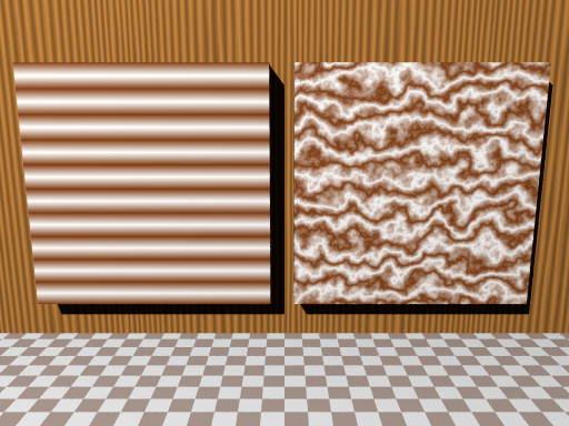
(c) 乱れ(turbulence)
turbulence により乱れを与えて、ピグメントパターンやノーマルをかき混ぜることができる。乱れの大きさを x,y,z 方向でコントロールしたいときは、乱れの大きさを1つの数値でなくベクトルで与える。
< warp - turbulence の構文 >
pigment {
warp {
turbulence <AMOUNT>
[ octaves COUNT ]
[ lamda AMOUNT ]
[ omega AMOUNT ]
}
}
pigment ピグメントのキーワード
warp ワープのキーワード
turbulence 乱れのキーワード
<AMOUNT>
乱れの大きさ (0~1)、x,y,z 方向別では値をベクトル記述
octaves COUNT乱れの計算ステップ数 1~10の整数 [デフォルト:6 ]
lamda AMOUNT直前の乱れとの相違値 [デフォルト:2.0 ]
omega AMOUNT直前の乱れとの相対的増減値 [デフォルト:0.5 ]
(c1) turbulence の効果
次の図13.2-4 (c1) は、marble(大理石)パターンを使用し、右側が turbulence 0 、左側が 0.8 を設定した例である。marble(大理石)パターンは、turbulence を使わないと、それらしく見えないことがわかる。
(左側)turbulence 0
図13.2-4 (c1) turbulence
∇ POV-Rayソース: 図13.2-4 (c1) turbulence
//------------- Fig. 13.2-4c1 turbulence
#version 3.7
#include "colors.inc"
#include "textures.inc"
global_settings
{ assumed_gamma 2.2 }
camera {
location <0.8, -10,5>
sky <0, 0, 1>
right <-image_width/image_height,0,0>
angle 60
look_at <0.8,0,3>
}
light_source { <-10, -25,20> rgb 1.5 }
//--------------------------color map
#declare CBM=
color_map {
[0.0 color rgb<1,0.5,0.2>*0.6]
[1.0 White*1.2]
}
//-------------------default (warp)
//--- turbulence 0
//--- octaves 6
//--- lamda 2
//--- omega 0.5
//================================== box (left)
box{0,1 scale <5,1,5>
pigment {
marble // <<<--------marble
color_map {CBM}
scale 0.5
rotate y*90
}
translate <-4.5,0,1>
}
//================================== box (right)
box{0,1 scale <5,1,5>
pigment {
marble // <<<--------marble
color_map {CBM}
warp {
turbulence 0.8 // <<<-------turbulence 0.8
}
scale 0.5
rotate y*90
}
translate <1,0,1>
}
//--------------------------------back wall
box{0,1 scale <20,1,10>
texture {DMFWood4 scale 3}
translate <-10,0.7,0>
}
//---------------------------------floor
#declare CA1=rgb<0.95,0.85,0.8>;
#declare CA2=rgb 1.3;
plane
{ z, 0
pigment {checker CA1 CA2 rotate x*90 scale 0.4 }
}
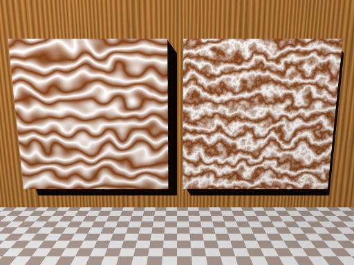
(c2) turbulence / octaves 効果
octaves(オクターブ)は計算のステップ数である。この値が小さいと乱れは穏やかなものになり、大きいと激しくなったりする。次の図13.2-4 (c2) は、turbulence 0.8 の設定に加えて、octaves の値を変えた例である。(octaves のデフォルト:6 )
(左側)turbulence 0.8 / octaves 1
図13.2-4 (c2) turbulence / octaves
∇ POV-Rayソース: 図13.2-4 (c2) turbulence / octaves
//------------- Fig. 13.2-4c2 turbulence / octaves
#version 3.7
#include "colors.inc"
#include "textures.inc"
global_settings
{ assumed_gamma 2.2 }
camera {
location <0.8, -10,5>
sky <0, 0, 1>
right <-image_width/image_height,0,0>
angle 60
look_at <0.8,0,3>
}
light_source { <-10, -25,20> rgb 1.5 }
//--------------------------color map
#declare CBM=
color_map {
[0.0 color rgb<1,0.5,0.2>*0.6]
[1.0 White*1.2]
}
//-------------------default (warp)
//--- turbulence 0
//--- octaves 6
//--- lamda 2
//--- omega 0.5
//================================== box (left)
box{0,1 scale <5,1,5>
pigment {
marble // <<<--------marble
color_map {CBM}
warp {
turbulence 0.8 // <<<-------turbulence 0.8
octaves 1 // <<<----------octaves 1
}
scale 0.5
rotate y*90
}
translate <-4.5,0,1>
}
//================================== box (right)
box{0,1 scale <5,1,5>
pigment {
marble // <<<--------marble
color_map {CBM}
warp {
turbulence 0.8 // <<<-------turbulence 0.8
octaves 10 // <<<----------octaves 10
}
scale 0.5
rotate y*90
}
translate <1,0,1>
}
//--------------------------------back wall
box{0,1 scale <20,1,10>
texture {DMFWood4 scale 3}
translate <-10,0.7,0>
}
//---------------------------------floor
#declare CA1=rgb<0.95,0.85,0.8>;
#declare CA2=rgb 1.3;
plane
{ z, 0
pigment {checker CA1 CA2 rotate x*90 scale 0.4 }
}
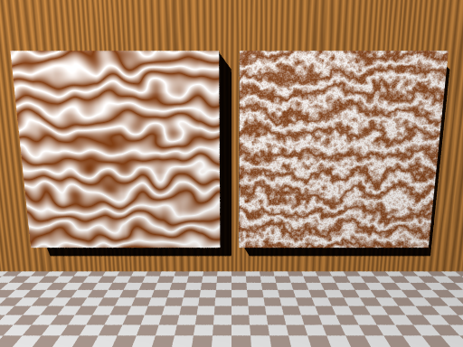
(c3) turbulence / lambda 効果
lambda(ラムダ)の数値は、乱れがその直前と比べて、その乱れの増減をコントロールする。lambda が小さいと穏やかになり、大きいと穏やかであるが複雑になる。次の図13.2-4 (c3) は、lambda の値の違いによる乱れの様子を示している。(octaves のデフォルト:2 )
(左側)turbulence 0.8 / lambda 0
図13.2-4 (c3) turbulence / lambda
∇ POV-Rayソース: 図13.2-4 (c3) turbulence / lambda
//------------- Fig. 13.2-4c3 turbulence / lambda
#version 3.7
#include "colors.inc"
#include "textures.inc"
global_settings
{ assumed_gamma 2.2 }
camera {
location <0.8, -10,5>
sky <0, 0, 1>
right <-image_width/image_height,0,0>
angle 60
look_at <0.8,0,3>
}
light_source { <-10, -25,20> rgb 1.5 }
//--------------------------color map
#declare CBM=
color_map {
[0.0 color rgb<1,0.5,0.2>*0.6]
[1.0 White*1.2]
}
//-------------------default (warp)
//--- turbulence 0
//--- octaves 6
//--- lamda 2
//--- omega 0.5
//================================== box (left)
box{0,1 scale <5,1,5>
pigment {
marble // <<<--------marble
color_map {CBM}
warp {
turbulence 0.8 // <<<-------turbulence 0.8
lambda 0 // <<<-----------lambda 0
}
scale 0.5
rotate y*90
}
translate <-4.5,0,1>
}
//================================== box (right)
box{0,1 scale <5,1,5>
pigment {
marble // <<<--------marble
color_map {CBM}
warp {
turbulence 0.8 // <<<-------turbulence 0.8
lambda 4 // <<<-----------lambda 4
}
scale 0.5
rotate y*90
}
translate <1,0,1>
}
//--------------------------------back wall
box{0,1 scale <20,1,10>
texture {DMFWood4 scale 3}
translate <-10,0.7,0>
}
//---------------------------------floor
#declare CA1=rgb<0.95,0.85,0.8>;
#declare CA2=rgb 1.3;
plane
{ z, 0
pigment {checker CA1 CA2 rotate x*90 scale 0.4 }
}
(c4) turbulence / omega 効果
omega(オメガ)の数値は、乱れがその直前と比べて、相対的な増減値を示す。値が小さいと穏やかになるが、大きいと小さい複雑な乱れが多くなる。次の図13.2-4 (c4) は、omega の値の違いによる乱れの様子を示している。(omega のデフォルト:0.5 )
(左側)turbulence 0.8 / omega 0
図13.2-4 (c4) turbulence / omega
∇ POV-Rayソース: 図13.2-4 (c4) turbulence / omega
//------------- Fig. 13.2-4c4 turbulence / omega
#version 3.7
#include "colors.inc"
#include "textures.inc"
global_settings
{ assumed_gamma 2.2 }
camera {
location <0.8, -10,5>
sky <0, 0, 1>
right <-image_width/image_height,0,0>
angle 60
look_at <0.8,0,3>
}
light_source { <-10, -25,20> rgb 1.5 }
//--------------------------color map
#declare CBM=
color_map {
[0.0 color rgb<1,0.5,0.2>*0.6]
[1.0 White*1.2]
}
//-------------------default (warp)
//--- turbulence 0
//--- octaves 6
//--- lamda 2
//--- omega 0.5
//================================== box (left)
box{0,1 scale <5,1,5>
pigment {
marble // <<<--------marble
color_map {CBM}
warp {
turbulence 0.8 // <<<-------turbulence 0.8
omega 0 // <<<------------omega 0
}
scale 0.5
rotate y*90
}
translate <-4.5,0,1>
}
//================================== box (right)
box{0,1 scale <5,1,5>
pigment {
marble // <<<--------marble
color_map {CBM}
warp {
turbulence 0.8 // <<<-------turbulence 0.8
omega 0.8 // <<<------------omega 0.8
}
scale 0.5
rotate y*90
}
translate <1,0,1>
}
//--------------------------------back wall
box{0,1 scale <20,1,10>
texture {DMFWood4 scale 3}
translate <-10,0.7,0>
}
//---------------------------------floor
#declare CA1=rgb<0.95,0.85,0.8>;
#declare CA2=rgb 1.3;
plane
{ z, 0
pigment {checker CA1 CA2 rotate x*90 scale 0.4 }
}
(d) マッピング
これはワープを利用した3Dマッピングであり、パターンを物体(オブジェクト)周囲に巻きつける機能がある。対象とする物体として cylindrical(円柱)、spherical(球)、toroidal(ドーナツ)があるが、どのような物体に対しても使用することができる。その他に planar(地層)、cubic(立方体)がある。
(d1) cylindrical(円柱)
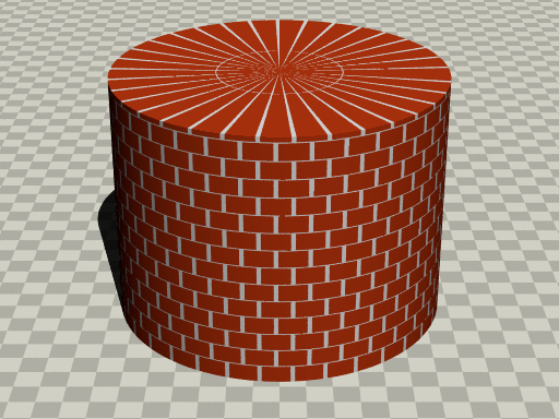
cylindrical(円柱)に対応するワープマッピングである。次の図13.2-4 (d1) cylindrical(円柱)は、brick(レンガ)パターンを円柱にマッピングしている。通常 brick は、平面に対してしかうまく機能しないがワープ機能で円柱に対応できている。
図13.2-4 (d1) cylindrical(円柱)
∇ POV-Rayソース: 図13.2-4 (d1) cylindrical(円柱)
//-------------------- Fig. 13.2-4d1 warp/cylindrical
#version 3.7
#include "colors.inc"
#include "textures.inc"
global_settings
{ assumed_gamma 2.2 }
//------------------------------ camera - light
camera{
location <0,-14,8>
sky <0, 0, 1>
right <-image_width/image_height,0,0>
look_at <0, 0, 1.2>
angle 25
}
light_source{ <100, -400, 500> color rgb 1.5}
//================================== warp / cylindrical
#declare CB1 = rgb<1,1,1>;
#declare CB2 = rgb<0.8,0.25,0.1>;
cylinder {0, z*3, 2
pigment {
brick CB1 CB2
brick_size <0.03,0.07,0.5>
mortar 0.004
warp{
cylindrical // <<<------------cylindrical
orientation z
}
rotate x*90
scale 3
}
}
//---------------------------------floor
#declare CA1=rgb<0.85,0.85,0.8>;
#declare CA2=rgb<0.85,0.85,0.8>*1.2;
plane{ z,0
pigment{checker CA1 CA2 scale 0.3 }
}
< warp - cylindrical の構文 >
pigment {
warp {
cylindrical
[ orientation <VECTOR> ]
[ dist_exp FLOAT ]
}
pigment ピグメントのキーワード
warp ワープのキーワード
cylindrical 円柱マッピングのキーワード
orientation <VECTOR>マッピング方向、x,y,zのベクトル [デフォルト:<0,1,0> ]
dist_exp FLOATy 軸からの指数距離、[デフォルト:0 ]
(d2) spherical(球)
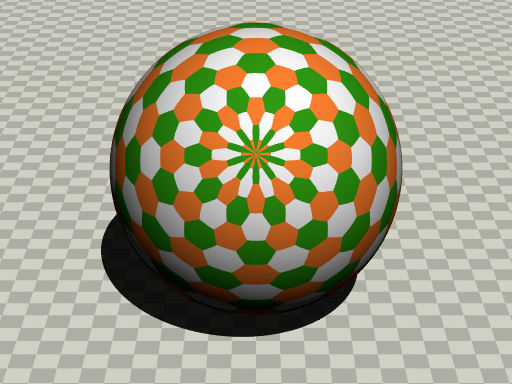
spherical(球)に対応するワープマッピングである。次の図13.2-4 (d2) spherical(球)は、hexagon(六角形)パターンを球にマッピングしている。通常 hexagon は、平面に対応するものであるが、ワープ機能で球にきれいに対応できている。
図13.2-4 (d2) spherical(球)
∇ POV-Rayソース: 図13.2-4 (d2) spherical(球)
//-------------------- Fig. 13.2-d2 warp/spherical
#version 3.7
#include "colors.inc"
#include "textures.inc"
global_settings
{ assumed_gamma 2.2 }
//------------------------------ camera - light
camera{
location <0,-14,8>
sky <0, 0, 1>
right <-image_width/image_height,0,0>
look_at <0, 0, 1.2>
angle 25
}
light_source{ <100, -400, 500> color rgb 1.5}
//================================== warp / spherical
#declare HC1=rgb<1,0.5,0.2>;
#declare HC2=rgb<1,1,1>;
#declare HC3=rgb<0.2,0.6,0.1>;
sphere {
0,1.8
pigment {
hexagon HC1 HC2 HC3
scale 0.03
warp {
spherical // <<<------------------spherical
orientation y
dist_exp 1
}
scale 2
}
rotate x*-30
translate <0,-1,2>
}
//---------------------------------floor
#declare CA1=rgb<0.85,0.85,0.8>;
#declare CA2=rgb<0.85,0.85,0.8>*1.2;
plane{ z, 0
pigment{ checker color CA1, color CA2 scale 0.3 }
}
< warp - spherical の構文 >
pigment {
warp {
spherical
[ orientation <VECTOR> ]
[ dist_exp FLOAT ]
}
pigment ピグメントのキーワード
warp ワープのキーワード
spherical 球マッピングのキーワード
orientation <VECTOR>マッピング方向、x,y,zのベクトル [デフォルト:<0,1,0> ]
dist_exp FLOAT原点からの指数距離、[デフォルト:0 ]
(d3) toroidal(ドーナツ)
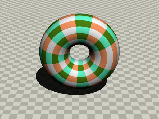
toroidal(ドーナツ)に対応するワープマッピングである。次の図13.2-4 (d3) toroidal(ドーナツ)は、square(正方形)を使用し、トーラスにマッピングしている。通常 square は、平面に対応するものであるが、ワープ機能でトーラスにきれいに対応できている。
図13.2-4 (d3) toroidal(ドーナツ)
∇ POV-Rayソース: 図13.2-4 (d3) toroidal(ドーナツ)
//-------------------- Fig. 13.2-4d3 warp/toroidal
#version 3.7
#include "colors.inc"
#include "textures.inc"
global_settings
{ assumed_gamma 2.2 }
//------------------------------ camera - light
camera{
location <0,-14,8>
sky <0, 0, 1>
right <-image_width/image_height,0,0>
look_at <0, 0, 1.2>
angle 25
}
light_source{ <100, -400, 500> color rgb 1.5}
//================================== warp / toroidal
#declare CB1 = rgb<1,1,1>;
#declare CB2 = rgb<1,0.6,0.4>;
#declare CB3 = rgb<0.3,0.5,0.1>;
#declare CB4 = rgb<0.4,1,0.8>;
torus {
1, 0.6
pigment {
square CB1 CB2 CB3 CB4
scale 0.04
warp {
toroidal // <<<----------toroidal
orientation y
dist_exp 1
major_radius 1
}
}
translate <0,-1,2>
}
//---------------------------------floor
#declare CA1=rgb<0.85,0.85,0.8>;
#declare CA2=rgb<0.85,0.85,0.8>*1.2;
plane{ z,0
pigment{checker CA1 CA2 scale 0.3 }
}
< warp - toroidal の構文 >
pigment {
warp {
toroidal
[ orientation <VECTOR> ]
[ dist_exp FLOAT ]
[ major_radius FLOAT ]
}
pigment ピグメントのキーワード
warp ワープのキーワード
toroidal ドーナツマッピングのキーワード
orientation <VECTOR>マッピング方向、x,y,zのベクトル [デフォルト:<0,1,0> ]
dist_exp FLOAT主半径からの指数距離、[デフォルト:0 ]
major_radius FLOAT主半径の大きさ、[デフォルト:1 ]
(d4) planar(平面)
planar(平面)は、物体形状に対応するワープマッピングとは違い、平面上のパターンを直角に押し出す機能がある。デフォルトでは、x-y 平面のパターンが z 軸に沿って押し出される。他のワープマッピングと併用できる。
次の図13.2-4 (d4) planar(平面)は、agate(めのう)パターンを使用している。立方体にマッピングされた、x-y 平面上の模様が z 軸方向に押し出されている。
図13.2-4 (d4) planar(平面)
∇ POV-Rayソース: 図13.2-4 (d4) planar(平面)
//-------------------- Fig. 13.2-4d4 warp/planar
#version 3.7
#include "colors.inc"
#include "textures.inc"
global_settings
{ assumed_gamma 2.2 }
//------------------------------ camera - light
camera{
location <0,-14,8>
sky <0, 0, 1>
right <-image_width/image_height,0,0>
look_at <0, 0, 1.2>
angle 25
}
light_source{ <100, -400, 500> color rgb 1.5}
//================================== warp / planar
#declare ACL=
color_map{[0.0 White ]
[0.5 Turquoise ]
[1.0 SlateBlue ] }
box {-1,1 scale 1.2
pigment {
agate
color_map{ACL}
warp { planar z 1.2 } //<<<------------ planar
}
translate <1.5,0,1>
}
box {-1,1 scale 1.2
pigment {
agate
color_map{ACL}
}
translate <-1.5,0,1>
}
//---------------------------------floor
#declare CA1=rgb<0.85,0.85,0.8>;
#declare CA2=rgb<0.85,0.85,0.8>*1.2;
plane{ z,0
pigment{checker CA1 CA2 scale 0.3 }
}
< warp - planar の構文 >
pigment {
warp {
planar [ <VECTOR> , FLOAT ]
}
pigment ピグメントのキーワード
warp ワープのキーワード
plana r平面マッピングのキーワード
<VECTOR>
マッピング方向、x,y,zのベクトル [デフォルト:<0,1,0> ]
FLOAT
主半径からの指数距離、[デフォルト:0 ]
(d5) cubic(立方体)
cubic(立方体)は、物体形状に対応するワープマッピングとは違い、原点を中心にとした立方体のUVマッピングを行う。原点(0,0)から(1,1)までの領域がマッピングの対象である。具体的には直方体であれば、例えば z 方向のサイズが一番小さければ、直方体の2つの x-y 平面上にマッピングが行われる。ワープマッピングは一番小さいサイズを検出して自動的に実行される。他の面は通常のマッピングがされる。
次の図13.2-4 (d5) cubic(立方体)は、leopard(豹)パターンを使用している。この立方体のサイズを変更すると自動的にワープマッピングも変化する。この図では、立方体の z サイズを 1 から 0.75、0.5、0.25 に変化させた様子を示している。
図13.2-4 (d5) cubic(立方体)
∇ POV-Rayソース: 図13.2-4 (d5) cubic(立方体)
//-------------------- Fig. 13.2-4d5 warp/cubic
#version 3.7
#include "colors.inc"
#include "textures.inc"
global_settings
{ assumed_gamma 2.2 }
//------------------------------ camera - light
camera{
location <0,-14,30> //z8
sky <0, 0, 1>
right <-image_width/image_height,0,0>
look_at <0, 0, 1.2>
angle 13
}
light_source{ <-400, -400, 500> color rgb 1.5}
//================================== warp / cubic
#declare ACL=
color_map{
[0 LightBlue*1.3 ]
[0.15 SkyBlue*1.4 ]
[0.5 White*1.2 ]
}
//-------------------------box 1
box {-1,1 scale 1
pigment {
leopard
color_map{ACL}
scale 0.1
}
translate <-1.5,1,1>
}
//--------------------------box 2
box {-1,1 scale z*0.75
pigment {
leopard
color_map{ACL}
scale 0.02
warp { cubic } // <<<----------- cubic
}
translate <1.5,1,1.25>
}
//--------------------------box 3
box {-1,1 scale z*0.5
pigment {
leopard
color_map{ACL}
scale 0.02
warp { cubic } // <<<----------- cubic
}
translate <1.5,-1.5,1.5>
}
//--------------------------box 4
box {-1,1 scale z*0.25
pigment {
leopard
color_map{ACL}
scale 0.02
warp { cubic } // <<<----------- cubic
}
translate <-1.5,-1.5,1.75>
}
//--------------------------------------floor
#declare CA1=rgb<0.85,0.85,0.8>;
#declare CA2=rgb<0.85,0.85,0.8>*1.2;
plane{ z,0
pigment{checker CA1 CA2 scale 0.3 }
}
< warp - cubic の構文 >
pigment {
warp {
cubic
}
pigment ピグメントのキーワード
warp ワープのキーワード
cubic 立方体マッピングのキーワード
13.2-5 乱れ(turbulence)(旧)
この turbulence(乱れ)は warp(ワープ)文を使わない。機能的には warp の turbulence とほぼ同じである。しかし、この turbulence の実行は、warp とは違って、パターンのオプション記述順に関係なく常に一番最初に実行される。この機能は、互換性のために残されている。
13.2-6 イメージマップ(image_map)
イメージマップを使用すると、2次元画像を3次元物体上に貼り付けることができる。
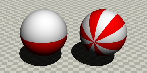
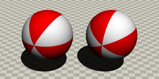
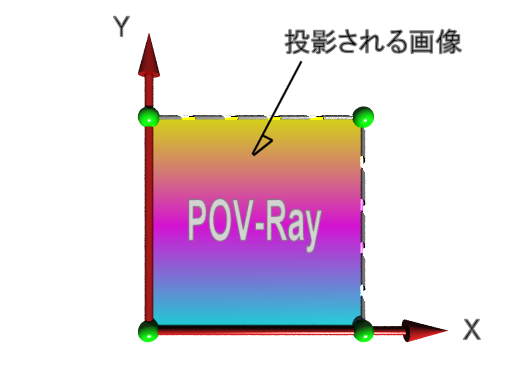
図13.2-6a イメージマップ
イメージマップはx-y平面に1x1の大きさで投影される。デフォルトでは、図13.2-6bのイメージは、図13.2-6cの向きで物体に貼り付けられる。イメージマップの投影法:▷「13.2 パターンのオプション」 参照
図13.2-6b イメージマップのもとになる2次元画像
図13.2-6c イメージマップの向きと大きさ
< image_map の構文 >
pigment {
image_map {
FILE_TYPE "filename"
[ once ]
[ map_type TYPE_NUM ]
[ interpolate 2 | interpolate 4 ]
}
}
pigment ピグメントのキーワード
image_map イメージマップのキーワード
FILE_TYPE
2次元画像のファイル形式を次の中から設定する。
FILE_NAME
2次元画像のファイル名の設定
once イメージ修正オプション ▷「13.2-7 ビットマップ修正」 参照
map_type TYPE_NUMイメージ修正オプション ▷「13.2-7 ビットマップ修正」 参照
interpolate 2
イメージ修正オプション ▷「13.2-7 ビットマップ修正」 参照
● 画像の透過率の修正 イメージを部分的に透明にするために、PNG, GIF, IFF の画像のカラーパレット番号に filter や transmit の値を設定できる。ファイル名の後に filter や transmit のキーワードを追加し、続いて2つの数、パレットナンバーと透過率を記述する。2つの値はコンマで区切る。
例)
image_map {
png "mypic.png"
filter 0, 0.5 // カラー 0 を 50% のフィルター透過にする。
filter 5, 1.0 // カラー 5 を 100% のフィルター透過にする。
transmit 8, 0.3 // カラー 8 を 30% のノンフィルター透過にする。
}
filter all VALUE や transmit all VALUE を使用して、イメージ全体に filter や transmit の値を与えることもできる。
例)
image_map {
png "stnglass.png"
filter all 0.9
}
※ filter と transmit の違い:▷「1.5 カラー」 参照
● PNGファイルの Alpha Channel PNGファイルには Alpha Channel があり、フィルターの記述なしで透過を実現できる。PNGでは、各カラーパレット番号に異なった透過率を与えることができる。画像編集アプリで、PNGのこの機能を利用すれば、透過率の編集ができる。また、イメージの中のカラーパレット番号のかわりに、その位置によって透過率を設定することもできる。
※ 注意 POV-Ray では transmit 0.0 では不透明で、1.0 で完全に透明になる。Alpha Channel は反対向きに 0~255 の範囲になる。Alpha Channel の 0 は透明で tramsmit 1.0 、Alpha Channel の 255 は不透明で transmit 0.0 に対応している。
13.2-7 ビットマップ修正
イメージマップ、バンプマップ、マテリアルマップでは、ビットマップ修正により3次元物体表面への2次元画像の貼り付けがコントルールされる。
● once イメージマップ、バンプマップ、マテリアルマップでは、マッピングは無限に繰り返される。ファイル名の後に once を記述すると、(0,0)~(1,1)以外の外側の領域は完全に透明になる。バンプマップでは、この外側の領域は平坦な面になる。マテリアルマップでは、この外側の領域はテクスチャリストの最初のものがテクスチャ化される。
● map_type map_type を設定することで物体形状に対応することができる。map_type のデフォルトは、平面マップで map_type 0 である。
map_type 0
平面マッピング、x-y 平面に 1x1 の大きさで投影され、全方向に無限に繰り返される。[ デフォルト ]
map_type 1
球面マッピング、y 軸方向周りにマッピングが行われる。once のキーワードは無効
map_type 2
円柱マッピング、y 軸方向の円柱に球状マッピングと同じように巻き付く。マップの高さは1(y=0~1)で、マッピングが繰り返される。once が有効
map_type 3
開発中
map_type 5
トーラスマッピング、トーラスは、半径が 1 で、中心が x-y 平面の原点に置かれているとする。マップの上端と下端は、トーラスの内側で互いに出会うように上下を包む。
例)
sphere{<0,0,0>,1
pigment{
image_map {
png "world.png"
map_type 1
}
}
}
● interpolate(補間)
interpolateは、ビットマップのギザギザを滑らかにするために使用する。
interpolate 2 interpolate 4より滑らかであるが、レンダリングは遅い。
interpolate 4 簡易的な補間を行う。レダリングはこちらのほうが速い。
通常は interpolate 2 を使用する。デフォルトでは補間は行われない。
(End) 13.テクスチャ2